A waste cable stripping recovery device

A recycling device and waste cable technology, which is applied in the direction of cable installation device, cable installation, electronic waste recycling, etc., can solve the problem that the complete separation of cable conductors and cable insulation can not be realized, the cable can not be peeled online, and the workload of recycling can be increased. and other issues to achieve the effect of facilitating reuse, reducing occupation and pollution, and realizing recycling

Active Publication Date: 2019-04-19
新昌县管富机械有限公司
View PDF7 Cites 1 Cited by
  • Summary
  • Abstract
  • Description
  • Claims
  • Application Information

AI Technical Summary

Problems solved by technology

[0005] The shortcomings of the above two structures are: when in use, the cutting of the cable insulation must be achieved through manual pulling and cooperation, and the complete separation of the cable conductor and the cable insulation cannot be achieved, and the manual pulling of the cable conductor will cause damage to the operator. Injury to the hand; and the online peeling of long cables cannot be realized, which increases the workload of recycling

Method used


Image

  • A waste cable stripping recovery device
  • A waste cable stripping recovery device
  • A waste cable stripping recovery device

Examples


Embodiment 1

[0053] A waste cable stripping recovery device, comprising a base 1, a winding mechanism arranged on the base 1, three lead wire mechanisms arranged on the base 1 and matched with the winding mechanism, arranged on the base 1 The peeling mechanism on the top and matched with the three lead wire mechanisms, the guiding mechanism arranged on the base 1 and matched with the peeling mechanism, and arranged on one side of the base for coordinated control of the winding The control mechanism 26 of mechanism, lead wire mechanism, peeling mechanism and guiding mechanism;

[0054] The winding mechanism includes a rotating shaft 4 arranged on the base 1, a rotating platform 21 arranged on the rotating shaft 4, a plurality of winding modules arranged on the rotating platform 21, and the winding module A transmission mechanism that cooperates and is arranged on the rotating platform 21 to drive the winding module;

[0055] The rewinding wheel includes a rewinding wheel 79, a plurality of...

Embodiment 2

[0072] It differs from Embodiment 1 in that: a guide plate 129 provided on the annular knife holder 124 for guiding the outer skin.

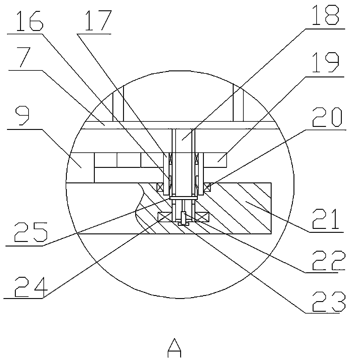
[0073] The upper half of the lead rod 11 is provided with a third telescopic rod.

[0074] The telescopic rod 22 is an electric telescopic rod with a rotary joint 23 at the bottom, and a brush is provided at the lower end of the electric telescopic rod.

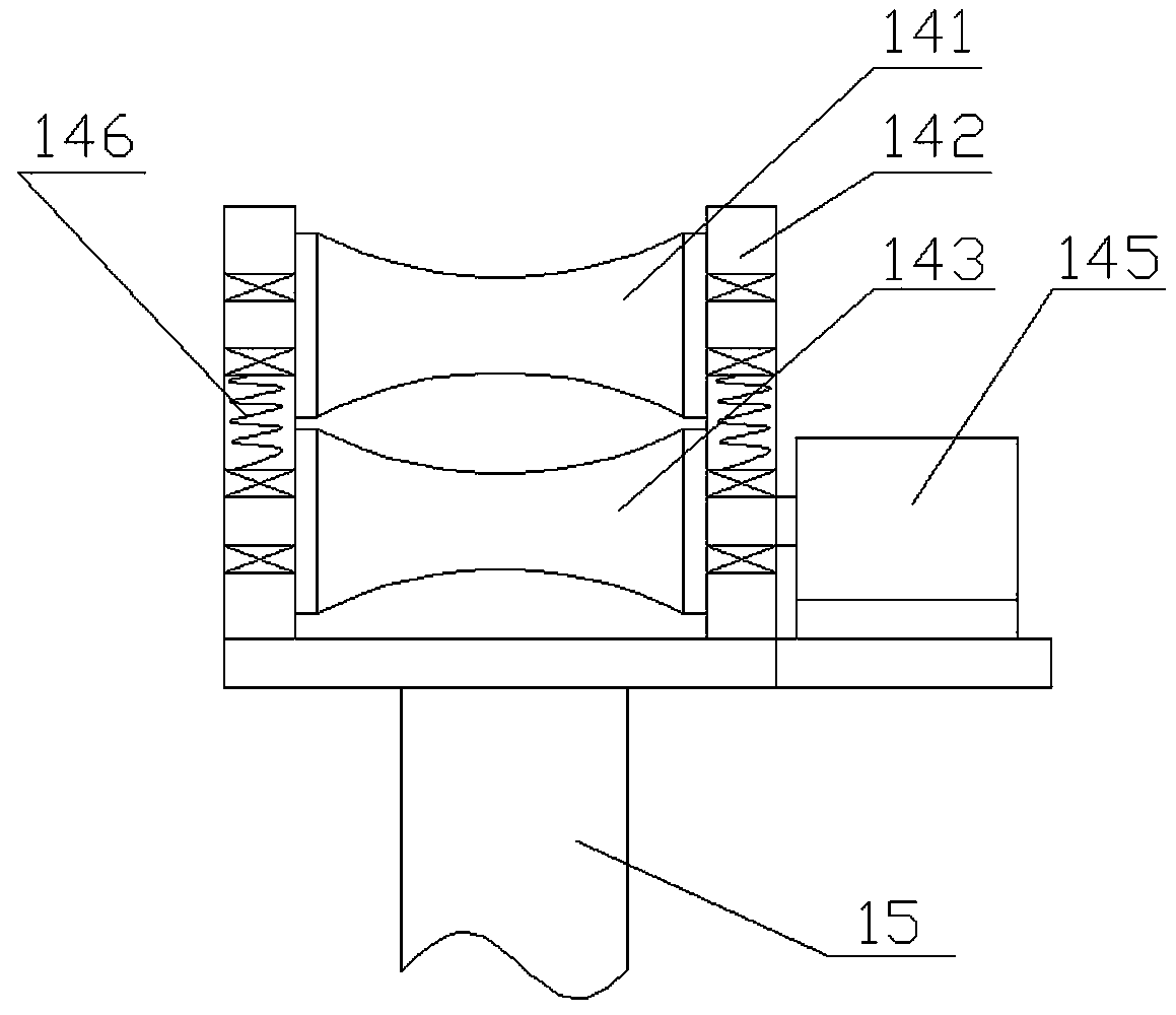
[0075] The upper end of the retractable telescopic rod 76 is provided with a retractable ring 80 for movably connecting with the tension rod 81 .

[0076] The outer wall of the upper end of the winding support rod 75 is provided with a plurality of auxiliary gear rods 77 for limiting the position of the wire reel.

[0077] In this embodiment, the base is set on the car or the wheels are set on the bottom surface, which can realize the free movement of the device and enhance the flexibility; and the guide plate adopted is a rectangular groove, which can well control the cut skin , to avoid dis...

Embodiment 3

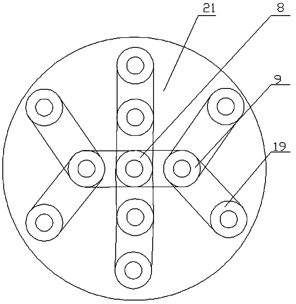
[0079] Such as Figure 10-12 As shown: the difference between it and the second embodiment is that four first positioning protrusions 28 for positioning are set on the rotating platform 21, and the first positioning protrusions 28 matched with the first protrusions 28 are set on the base 1. a positioning switch 31, and the first positioning switch 31 is interconnected with the control mechanism 26;

[0080] Four second positioning projections 29 for positioning are arranged on the lower end surface of the winding wheel, and a second positioning switch 30 matched with the second positioning projections 29 is provided on the rotating platform 21, and The second positioning switch 30 is connected to the control mechanism 26 for signals.

[0081] The first positioning protrusion and the second positioning protrusion adopted in this embodiment are all four-sided platforms; and the first positioning protrusion adopted can also be arranged on the rotating platform, and the protrusio...


PUM


Abstract

The invention provides a waste cable peeling recovery device. The waste cable peeling recovery device comprises a base, a rolling mechanism arranged on the base, a plurality of lead mechanisms which are arranged on the base and are matched with the rolling mechanism, a peeling mechanism which is arranged on the base and is matched with the lead mechanisms, a guide mechanism which is arranged on the base and is matched with the peeling mechanism, and a control mechanism arranged on one side of the base for carrying out coordination control on the rolling mechanism, the lead mechanisms, the peeling mechanism and the guide mechanism; the base is used as a substrate, the rolling mechanism, the lead mechanisms matched with the rolling mechanism and the peeling mechanism matched with the lead mechanisms are arranged on the base, in order to avoid the phenomenon of instability during peeling, the guide mechanism is arranged at the front end of the peeling mechanism, rapid separation is realized preferably through cooperative regulation of the control mechanism, metal and skin are stored respectively, a wire coil can be rapidly taken down by adopting a shrinkable rolling wheel, and efficient recovery operation in long line is realized.

Description

technical field [0001] The invention relates to the technical field of waste and old cable peeling and recycling devices, in particular to a waste and old cable peeling and recycling device. Background technique [0002] With the continuous development of the national economy and the strong advocacy of environmental protection, mechanical equipment using coal and petroleum as raw materials is gradually being replaced by electrical equipment, such as electric boilers, electric vehicles, etc. The changes in the structure of such products are invisible. The rapid increase in the demand for electricity caused by electricity, so electric power-related companies have developed a variety of high-load, high-power transmission equipment to meet the needs of the current situation. Among them, the promotion and use of overhead transmission lines with insulated cables has effectively avoided the failure of ordinary transmission lines Many problems, such as large energy loss, have improv...

Claims


Application Information

Patent Timeline
Patent Type & Authority Patents(China)
IPC IPC(8): H01B15/00H02G1/12
CPCH01B15/005H02G1/126Y02W30/82
Inventor 不公告发明人
Owner 新昌县管富机械有限公司
Why Eureka
Try Eureka