Quantitative dispensing device for intravenous configuration

A dispensing device and intravenous technology, applied in the direction of mixer accessories, dissolving, mixing machines, etc., can solve the problems of inability to quantitatively configure different proportions of liquid medicine, easy misdosing, low degree of automation, etc.

Inactive Publication Date: 2021-12-31
THE THIRD XIANGYA HOSPITAL OF CENT SOUTH UNIV
View PDF1 Cites 2 Cited by
  • Summary
  • Abstract
  • Description
  • Claims
  • Application Information

AI Technical Summary

Problems solved by technology

[0006] The above configuration rack cannot quantitatively configure different proportions of liquid medicine, the degree of automation is low, and manual configuration is still required, and there are still problems of easy mis-match and mis-match;

Method used


Image

  • Quantitative dispensing device for intravenous configuration
  • Quantitative dispensing device for intravenous configuration
  • Quantitative dispensing device for intravenous configuration

Examples


Embodiment 1

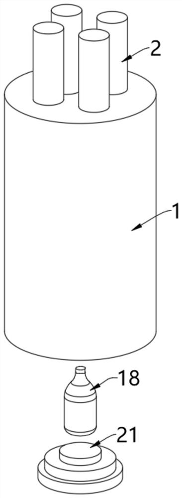
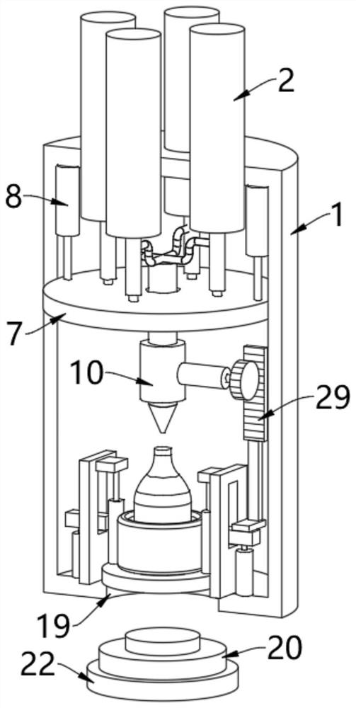
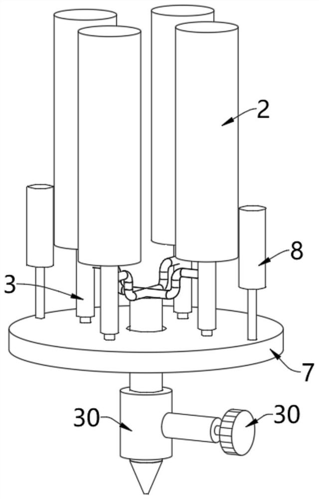
[0046] see Figure 1-Figure 5 , a quantitative drug dispensing device for intravenous configuration, including an outer cylinder 1, and several medicine tanks 2 are uniformly arranged on the top of the outer cylinder 1. In this embodiment, four medicine tanks 2 are arranged, and the inside of the four medicine tanks 2 Different liquid medicines are stored respectively, and of course different numbers of medicine tanks 2 can also be arranged according to the needs. The bottom of each medicine tank 2 is fixedly equipped with a medicine outlet pipe 3 , and the inner wall of the medicine outlet pipe 3 is movably provided with a control plug 5 . The control plug 5 is fixedly mounted on the top of the output shaft of the first push rod 6, and the first push rod 6 is fixedly mounted on the top of the supporting plate 7, and the edge of the top of the supporting plate 7 is fixedly connected with the output shaft of the second push rod 8, the second The second push rod 8 is fixedly ins...

Embodiment 2

[0054] see Figure 6-Figure 8 , on the basis of Embodiment 1, two side plates 11 are arranged opposite to the left and right sides of the inner bottom wall of the outer cylinder 1, and the insides of the two side plates 11 are all provided with movable grooves 12, and the insides of the two movable grooves 12 are both Control rods 13 are movable, and the bottoms of the outward ends of the two control rods 13 are fixedly connected with the output shaft of the third push rod 14, and the third push rod 14 is fixedly installed on the inner bottom wall of the outer cylinder 1, and the third push rod 14 operation can drive the control rod 13 on the top of its output shaft to rise or fall;

[0055] The inward ends of the two control rods 13 are fixedly connected with vertical tubes 15, and the two vertical tubes 15 are fixedly installed on the left and right sides of the outer wall of the bottom ring 16 respectively. Ring 16 ascends or descends;

[0056] For this example, see Fig...

Embodiment 3

[0061] see figure 2 with Image 6 , on the basis of Embodiment 1 and Embodiment 2, a vertical bar 28 is fixedly installed on the top of one of the control rods 13, and a rack 29 is fixedly installed on the top of the vertical bar 28, and a gear 30 is engaged with the outer wall of the rack 29, The center of the gear 30 is fixedly connected with the valve plate of the control valve 10 through the control shaft 31. When the third push rod 14 runs through the control rod 13, the vertical tube 15 and the airbag ring 17 to drive the infusion bottle 18 to move upward, the control rod 13 will also move upward. The vertical bar 28 drives the rack 29 to move upward, and the rack 29 moves upward to drive the gear 30 meshed with its outer wall to rotate. The rotation of the gear 30 through the control shaft 31 can make the valve plate of the control valve 10 rotate, thereby opening the control valve 10, the control valve After 10 is opened, the medicinal liquid in the dispensing pipe 9...


PUM


Abstract

The invention relates to the technical field of medicine dispensing devices, and discloses a quantitative medicine dispensing device for intravenous configuration. The device comprises an outer cylinder, a plurality of medicine tanks are evenly arranged at the top of the outer cylinder, medicine outlet pipes are fixedly installed at the bottoms of the medicine tanks, and control plugs are movably arranged on the inner walls of the medicine outlet pipes; and the control plug is fixedly mounted at the top of an output shaft of the first push rod; when the third push rod operates to enable the infusion bottle to move upwards, the control rod drives the rack to move upwards through the vertical rod, and the rack moves upwards to enable the valve plate of the control valve to rotate through the gear and the control shaft, so that the control valve is opened; after the control valve is opened, the liquid medicine in the preparation pipe can be discharged; so that an effect that the control valve can be synchronously opened when the infusion bottle moves upwards to be in butt joint with the configuration pipe is achieved; finally, after liquid medicine is filled, the infusion bottle can descend through the third push rod, the control valve can also be synchronously closed, manual control over the control valve is unnecessary, and the automation degree is higher.

Description

technical field [0001] The invention relates to the technical field of dispensing devices, in particular to a quantitative dispensing device for intravenous configuration. Background technique [0002] Intravenous infusion therapy has the advantages of quick effect, high bioavailability, controllable drug input speed and input volume, etc. It is one of the most common and common clinical treatment methods. The proportion of intravenous infusion in hospitalized patients in my country is as high as 80% The above is 20%-30% higher than that of foreign developed countries; at the same time, intravenous administration is also the most demanding way among all administration methods, because once a problem occurs in intravenous administration, its loss is irreparable; [0003] In the prior art, the dispensing work in intravenous infusion is generally completed by the nurses in each ward in their respective treatment rooms, and the nurses prepare bottled liquids of different specific...

Claims


Application Information

Patent Timeline
Patent Type & Authority Applications(China)
IPC IPC(8): B01F15/04B01F15/02B01F15/00
Inventor 柳威
Owner THE THIRD XIANGYA HOSPITAL OF CENT SOUTH UNIV
Why Eureka
Try Eureka