Nested box type floating disc structure

A nested, floating disc technology, applied in the direction of containers, packaging, transportation and packaging, etc., can solve the problems of safety accidents, structural asymmetry, uneven force, etc.

Pending Publication Date: 2021-12-31
江苏星亚迪环境科技有限公司
View PDF0 Cites 0 Cited by
  • Summary
  • Abstract
  • Description
  • Claims
  • Application Information

AI Technical Summary

Problems solved by technology

[0003] Existing floating discs have different structures, such as a floating disc assembled from a large number of rectangular cubic structures with different volumes and bolts. The structure of this kind of floating disc is asymmetric after assembly, resulting in unequal buoyancy and uneven force, which is easy to cause The torsional force leads to rollover and safety accidents, and a large number of mounting bolts and a large number of structural counterweight devices will cause loss of manpower and material resources

Method used


Image

  • Nested box type floating disc structure
  • Nested box type floating disc structure
  • Nested box type floating disc structure

Examples


Embodiment 1

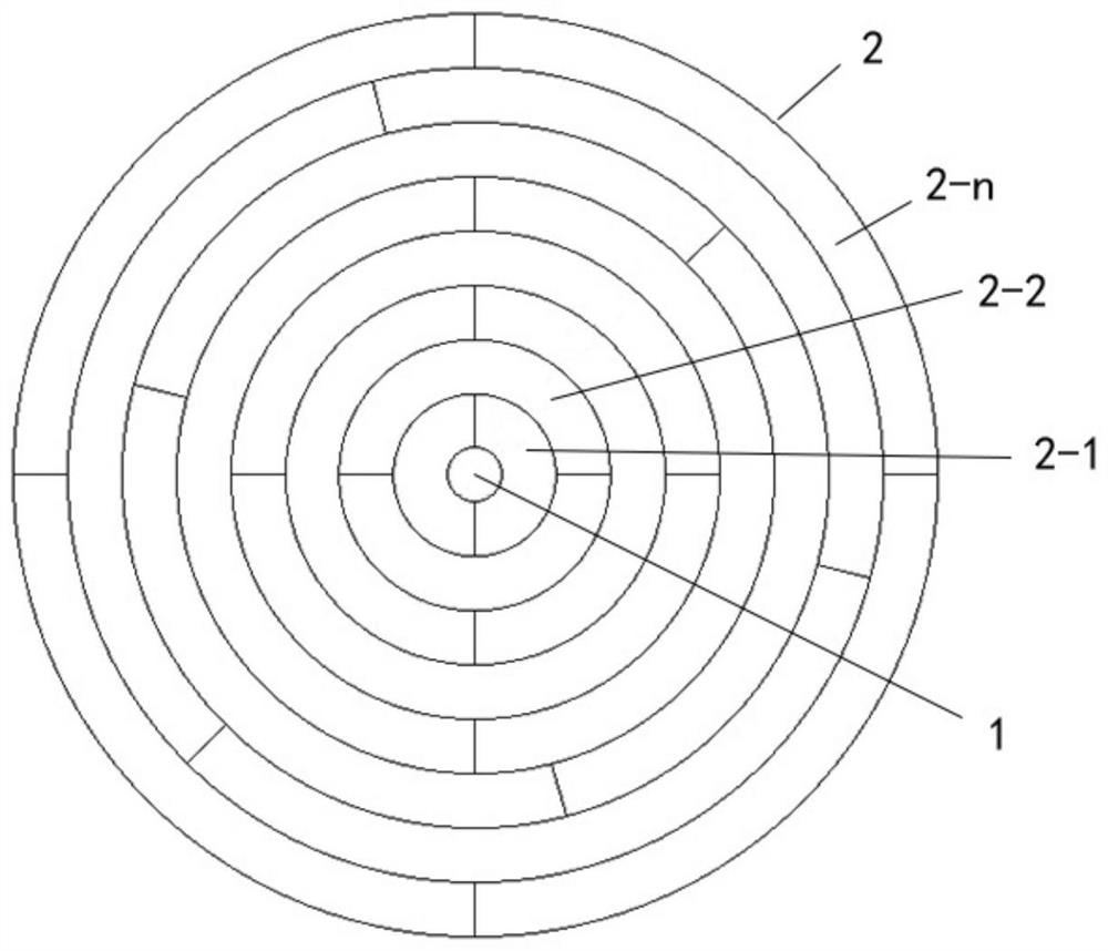
[0023] figure 1 It is a nested box-type floating disc structure shown in a feasible embodiment of the present application. The floating disc structure includes: a nested intermediate body 1 and a nested assembly 2 surrounding the outer periphery of the nested intermediate body 1; The nesting intermediate body 1 and the nesting assembly 2 are connected by inner and outer ring buckles 3 .

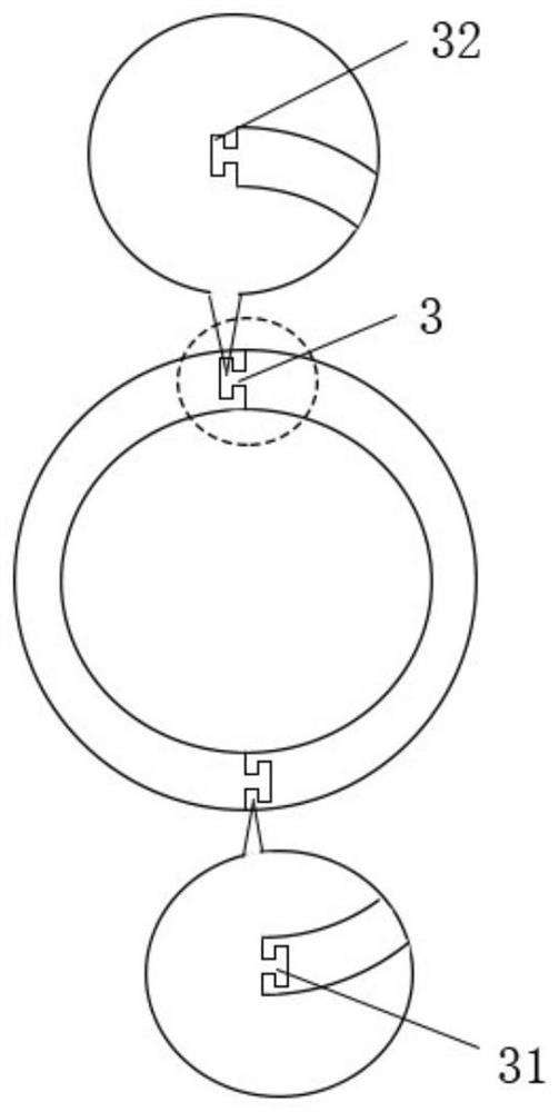
[0024] figure 2 A schematic cross-sectional view of an inner and outer ring buckle 3 is shown, figure 2 The inner and outer ring buckles 3 include an inner ring buckle 31 and an outer ring buckle 32, and the inner ring buckle 31 and the outer ring buckle 32 are both arranged on the side wall of the buoyancy unit.

[0025] In a feasible implementation, the inner ring buckle 31 is a buckle that is recessed inward along the side wall of the buoyancy unit to form a T-shaped groove, and the outer ring buckle 32 is convex outward along the side wall of the buoyancy unit. Pull up to form a T-sh...

Embodiment 2

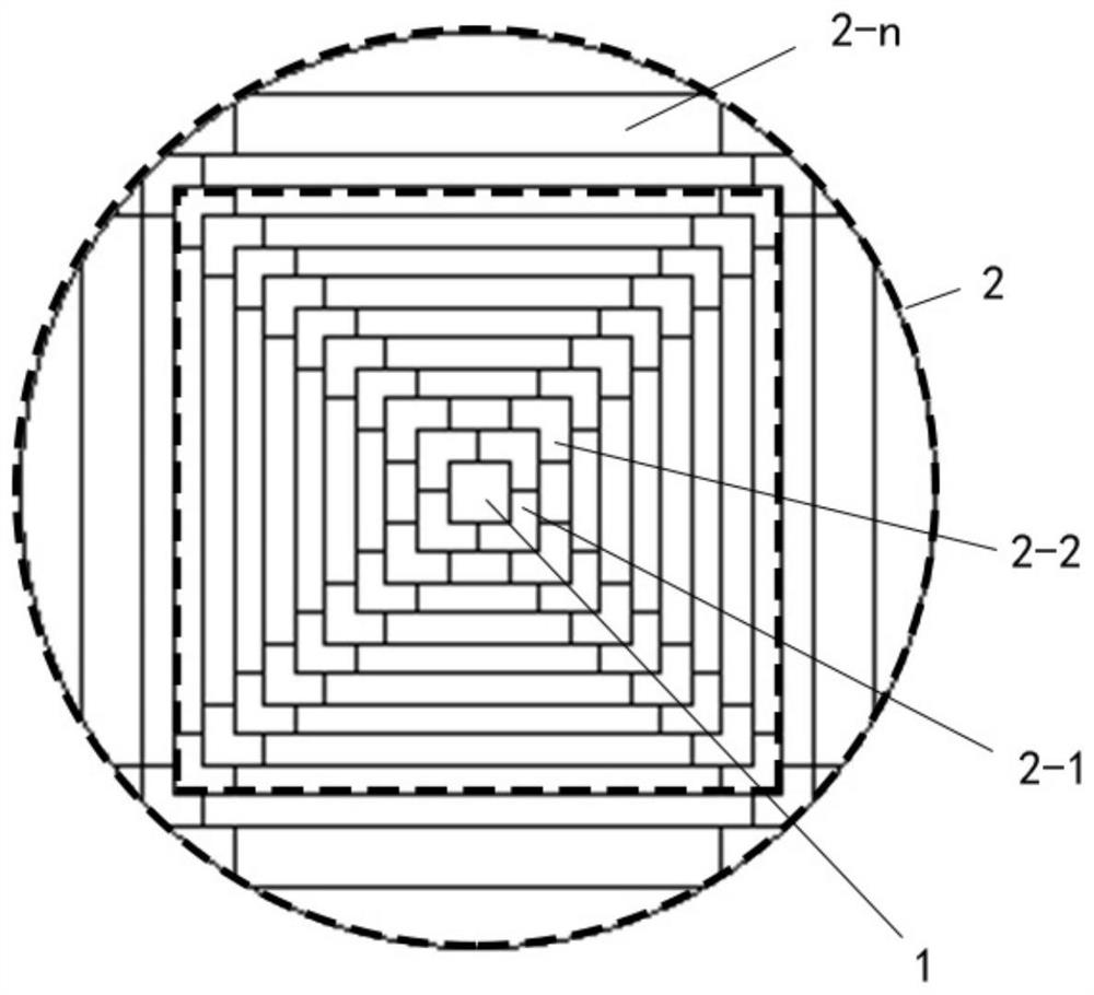
[0041] image 3 It is a nested box-type floating disc structure shown in a feasible embodiment of the present application. The floating disc structure includes: a nested intermediate body 1 and a nested assembly 2 surrounding the outer periphery of the nested intermediate body 1; The nesting intermediate body 1 and the nesting assembly 2 are connected by inner and outer ring buckles 3 .

[0042] In a feasible implementation, the inner ring buckle 31 is a buckle that is recessed inward along the side wall of the buoyancy unit to form a T-shaped groove, and the outer ring buckle 32 is convex outward along the side wall of the buoyancy unit. Pull up to form a T-shaped raised buckle.

[0043] It should be noted that, in actual production, it is necessary to install connecting fixing bolts or bayonet sockets on the upper and lower sides of the adjacent annular assemblies to increase the stability of the overall structure.

[0044] In a feasible implementation manner, multiple inn...

Embodiment 3

[0059] Figure 4 It is a nested box-type floating disc structure shown in a feasible embodiment of the present application. The floating disc structure includes: a nested intermediate body 1 and a nested assembly 2 surrounding the outer periphery of the nested intermediate body 1; The nesting intermediate body 1 and the nesting assembly 2 are connected by inner and outer ring buckles 3 .

[0060] In a feasible implementation, the inner ring buckle 31 is a buckle that is recessed inward along the side wall of the buoyancy unit to form a T-shaped groove, and the outer ring buckle 32 is convex outward along the side wall of the buoyancy unit. Pull up to form a T-shaped raised buckle.

[0061] In a feasible implementation manner, multiple inner and outer ring buckles 3 are provided on the side wall of the buoyancy unit.

[0062] It should be noted that the present application is not limited to the use of this inner and outer ring buckle, and inner and outer ring buckles in other...


PUM


Abstract

The invention discloses a nested box type floating disc structure. The floating disc structure comprises a nested middle body and a nested combination body surrounding the periphery of the nested middle body, wherein the nested middle body and the nested combination body are connected through an inner ring buckle and an outer ring buckle; the nested combination body is composed of a plurality of sub combination bodies; each sub combination body is of an axisymmetric structure; the sub combination bodies comprise the first sub combination body, the second sub combination body,..., and the nth sub combination body which sequentially surround the periphery of the nested middle body; and every two of the first sub combination body, the second sub combination body,..., and the nth sub combination body are connected through an inner ring buckle and an outer ring buckle. According to the nested box type floating disc structure provided by the invention, stress is stable and conduction is uniform through the structural arrangement of the nested box type floating disc structure, the strength problem under a beam-free structure is solved, use of mounting bolts is greatly reduced, uneven stress is reduced, structural balance weight does not need to be used for reinforcement, dismounting and mounting are convenient, and the occurrence rate of safety accidents such as rollover is reduced.

Description

technical field [0001] The present application relates to the technical field of oil storage, in particular to a nested box-type floating disc structure. Background technique [0002] There are a variety of toxic and harmful media in the petrochemical industry, and these toxic and harmful media need to be stored in oil storage tanks. As the medium in the oil storage tank increases or decreases during use, the medium in the oil storage tank is often in a non-full state. At this time, the gap between the medium surface and the top of the oil storage tank The distance becomes the volatilization space of the medium, because the toxic and harmful medium volatiles at the top are not conducive to recycling, and the more volatiles in the top medium, the greater the pressure in the oil storage tank, the greater the toxicity hazard, and some medium volatiles may explode Dangerous and extremely difficult to handle. Therefore, in order to limit the volatilization of the medium, a floa...

Claims


Application Information

Patent Timeline
Patent Type & Authority Applications(China)
IPC IPC(8): B65D88/34B65D90/38
CPCB65D88/34B65D90/38
Inventor 胡兆超张涛
Owner 江苏星亚迪环境科技有限公司
Why Eureka
Try Eureka