Microbial fermentation tank capable of defoaming

A technology of microbial fermentation and fermenter, which is applied in specific-purpose bioreactor/fermenter, bioreactor/fermenter combination, enzymology/microbiology device, etc. Eliminate foam, affect the fermentation efficiency of the fermenter and other problems, so as to improve the stirring effect, the fermentation work is smooth, and the safe use is ensured.

Inactive Publication Date: 2021-12-31
刘月
View PDF1 Cites 0 Cited by
  • Summary
  • Abstract
  • Description
  • Claims
  • Application Information

AI Technical Summary

Problems solved by technology

In the process of biological fermentation, microorganisms continue to grow, reproduce and metabolize, forming a large amount of gas and foam. If the foam is too large or the foam layer is too thick, an isolation layer will be formed, which will affect the normal progress of biological fermentation. However, the existing biological fermentation tank Most of them do not have the function of defoaming, and cannot eliminate the foam in the biological fermentation tank very well
[0003] In the patent CN202020171081.2 - a microbial fermentation tank capable of defoaming, a height adjustment component is provided. When bubbles appear on the surface of the fermentation raw material, the height of the defoaming component can be adjusted through the height adjustment component, so that the defoamer can be combined with the The surface of the fermentation material is located at the same level, and then the overall height of the defoaming component can be adjusted to solve the technical problem in the prior art that only a certain height of the surface air bubbles of the fermentation material can be eliminated
[0004] However, when adjusting the height of the above-mentioned patent, the staff needs to visually measure the height of the fermentation broth, and then adjust the height of the defoaming component to a suitable position. The height adjustment is not suitable, and it also seriously affects the fermentation efficiency of the fermenter

Method used


Image

  • Microbial fermentation tank capable of defoaming
  • Microbial fermentation tank capable of defoaming
  • Microbial fermentation tank capable of defoaming

Examples


Embodiment Construction

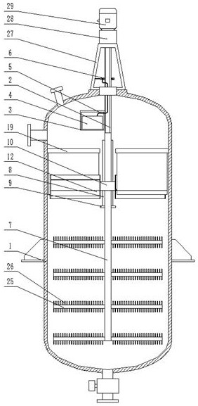
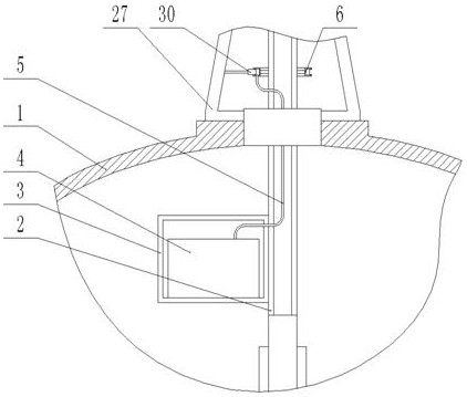
[0028] The present invention will be specifically described below in conjunction with the accompanying drawings, such as Figure 1-6 shown.

[0029] In this device, the device is powered by being connected to an external power source, and the external power source is electrically connected to the drive motor 29 and the electric slider 30 for power supply, so as to control the operation of the device.

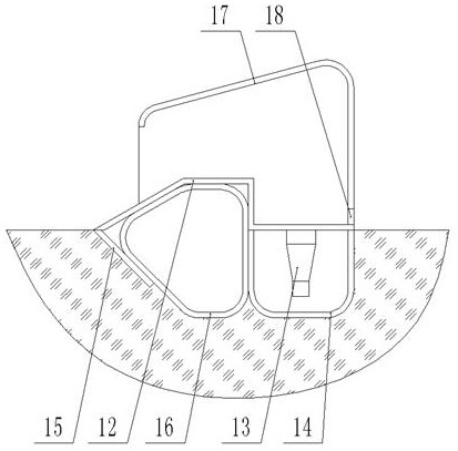
[0030] The creative point of this scheme is to adjust the structural design of the collection ultrasonic defoaming device, combined with the attachment figure 1 , attached figure 2 , attached image 3 and attached Figure 4The adjustment collection type ultrasonic defoaming device includes a stirring sleeve 2 on the inside of the fermentation tank body 1, the stirring sleeve 2 is movably connected with the fermentation tank body 1 through a mechanical seal, and a sealing box is installed on one side surface of the stirring sleeve 2 Body 3, an ultrasonic generator 4 is insta...


PUM


Abstract

The invention discloses a microbial fermentation tank capable of defoaming. The microbial fermentation tank comprises a fermentation tank body, an adjusting and collecting type ultrasonic defoaming device is arranged in the fermentation tank body, a floating type foam shielding device is arranged in the fermentation tank body, and a sawtooth-shaped stirring device is arranged on the lower portion in the fermentation tank body. According to the device, the n-shaped defoaming seat is suspended on fermentation liquor by utilizing buoyancy of the supporting air bag, foams in the fermentation tank are collected through rotation of the n-shaped defoaming seat, then the foams are subjected to defoaming treatment through ultrasonic waves, the foams in the fermentation tank can be quickly and effectively eliminated, and meanwhile, the foams are intensively collected for defoaming, a high-power ultrasonic generator is not needed, so that the cost of the device is reduced, the n-shaped defoaming seat can effectively shield foams when rotating through the shielding cloth floating above fermentation liquor, the foams are prevented from synchronously rotating along with the rotation of the n-shaped defoaming seat, and the defoaming efficiency of the device is improved.

Description

technical field [0001] The invention relates to the field of biochemical related equipment, in particular to a microbial fermentation tank capable of defoaming. Background technique [0002] The biological fermentation tank is an external environment device for microorganisms to produce, reproduce and form products during the fermentation process. It replaces the traditional fermentation container. Compared with the traditional fermentation container, it has obvious advantages. Air provides a good fermentation environment, and can implement measures such as stirring and shaking to promote the growth of microorganisms. It belongs to the commonly used biological fermentation equipment. In the process of biological fermentation, microorganisms continue to grow, reproduce and metabolize, which will form a large amount of gas and generate a large amount of foam. If the foam is too large or the foam layer is too thick, an isolation layer will be formed, which will affect the norma...

Claims


Application Information

Patent Timeline
Patent Type & Authority Applications(China)
IPC IPC(8): C12M1/42C12M1/21C12M1/02C12M1/00
CPCC12M23/02C12M27/02C12M35/04C12M41/02
Inventor 刘月
Owner 刘月
Why Eureka
Try Eureka