Pipe pile structure anchored by steel strands and manufacturing method

A technology for steel strands and pipe piles, which is used in foundation structure engineering, excavation, sheet pile walls, etc. The effect of pulling the bearing capacity

Pending Publication Date: 2021-12-31
NINGBO CONSTR GUANGTIAN COMPONENT PART +1
View PDF3 Cites 0 Cited by
  • Summary
  • Abstract
  • Description
  • Claims
  • Application Information

AI Technical Summary

Problems solved by technology

The uplift resistance of traditional pipe piles mainly depends on the friction between the pile body and the soil, but the pile body of the pipe pile has a high roughness grade and a small friction coefficient with the soil, which makes the pullout resistance of the pipe pile poor.

Method used


Image

  • Pipe pile structure anchored by steel strands and manufacturing method

Examples


Embodiment 1

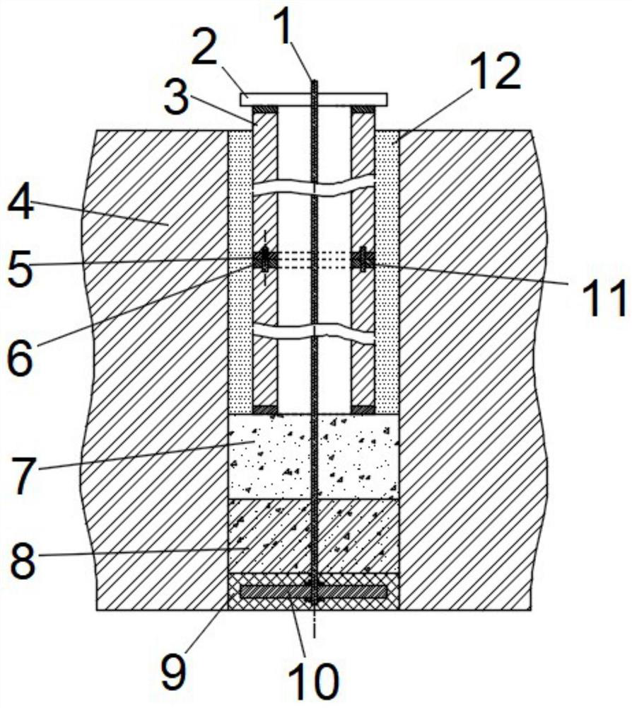
[0026] Refer to attached figure 1 As shown, a pipe pile structure anchored by steel strands includes: pipe pile device, steel strand 1, basement floor 2, anchor plate 10, prefabricated plate 9, concrete layer 8, gravel layer 7 and gap cement slurry layer 12. The bottom end of the steel strand 1 is fixedly installed on the anchor plate 10, the top end of the steel strand 1 is fixed on the basement floor 2, the basement floor 2 is installed on the top of the pipe pile device, and the anchor plate 10 is pre-buried in the prefabricated plate 9, The prefabricated slab 9 is placed at the bottom of the well, the top of the prefabricated slab 9 is the poured concrete layer 8, the crushed stone layer 7 is on the top of the concrete layer 8, the pipe pile device is sunk into the top of the crushed stone layer 7, and the gap cement slurry layer 12 is poured on the top of the pipe pile. The gap between the pile device and the well wall. The bottom end of the steel strand 1 is fixedly con...

Embodiment 2

[0029] A method for manufacturing a pipe pile anchored by a steel strand, comprising the steps of:

[0030] 1), use the geological drilling rig to drill down on the pile position, and the drilling depth will be greater than the design depth of the pipe pile 3;

[0031] 2), one end of the steel strand 1 is fixedly installed on the anchor plate 10, then put into the prefabricated mold, and the anchor plate 10 is pre-embedded in the prefabricated plate 9;

[0032] 3), lower the prefabricated plate 9 with the steel strand 1 into the borehole until it sinks into the bottom of the borehole;

[0033] 4) There is a large amount of water at the bottom of the drilled well. Use the conduit method to penetrate the conduit into the borehole until an appropriate amount of concrete is poured above the prefabricated slab 9 to form a concrete layer 8. During the hardening process of the concrete layer 8, keep a steel strand pull state;

[0034] 5), the pipe pile 3 is connected to the pile th...


PUM


Abstract

The invention discloses a pipe pile structure anchored by steel strands and a manufacturing method, and belongs to the technical field of pipe piles. The pipe pile structure comprises a pipe pile device, a steel strand, a basement bottom plate, an anchoring plate, a prefabricated plate, a concrete layer, a gravel layer and an interstitial cement paste layer; the bottom end of the steel strand is fixedly installed on the anchoring plate, the top end of the steel strand is fixed to the basement bottom plate, the basement bottom plate is installed at the top end of the pipe pile device, the anchoring plate is embedded in the prefabricated plate, the prefabricated plate is placed at the bottom end of a drilling well, the top end of the prefabricated plate is the poured concrete layer, the gravel layer is arranged at the top end of the concrete layer, and the pipe pile device sinks into the top end of the gravel layer. The interstitial cement paste layer is poured into a gap between the pipe pile device and a well wall. According to the pipe pile structure anchored by the steel strands and the manufacturing method, the anchoring plate is pre-buried at the bottom end of a drill hole, the basement bottom plate is placed at the top end of a pipe pile, and the steel strand is connected with the anchoring plate and the basement bottom plate, so that the uplift bearing capacity of the pipe pile is enhanced, and corrosion prevention of the pipe pile is also facilitated.

Description

technical field [0001] The invention relates to the technical field of pipe piles, in particular to a steel strand anchored pipe pile structure and a manufacturing method. Background technique [0002] Pipe piles are widely used in engineering, especially in coastal soft soil areas, and are widely used in various engineering piles and foundation pit enclosure piles. With the expansion of the application field of pipe piles, the requirements for the application of pipe piles are getting higher and higher. For piled raft foundations in basements with shallow groundwater levels, if pipe piles are used, they also need to have a higher uplift bearing capacity. The uplift resistance of traditional pipe piles mainly depends on the friction between the pile body and the soil, but the pile body of the pipe pile has a high roughness level and a small friction coefficient with the soil, which makes the pullout resistance of the pipe pile poor. Contents of the invention [0003] In ...

Claims


Application Information

Patent Timeline
IPC IPC(8): E02D17/04E02D5/58E02D5/52E02D5/50
CPCE02D17/04E02D5/58E02D5/526E02D5/50
Inventor 袁盛何建明查支祥潘崇根
Owner NINGBO CONSTR GUANGTIAN COMPONENT PART
Why Eureka
Try Eureka