Novel water pump

A water pump, a new type of technology, applied in the direction of pump components, pump control, variable-capacity pump components, etc., can solve the problems that the drainage pipe cannot automatically spray at multiple angles, the spraying distance is fixed, and it is inconvenient to use, so as to speed up flow mixing and speed up Circulation, the effect of expanding the spraying area

Pending Publication Date: 2021-12-31
安徽川子泵阀密封有限公司
View PDF11 Cites 0 Cited by
  • Summary
  • Abstract
  • Description
  • Claims
  • Application Information

AI Technical Summary

Problems solved by technology

The drainage pipe of the existing water pump cannot automatically perform multi-angle spraying, and the water pressure at the port of the drainage pipe is stable, resulting in a fixed spraying distance. In addition, the water cooling box installed outside the existing drive motor needs to be frequently sprayed to the inside when it is in use. Add cold water, inconvenient to use

Method used


Image

  • Novel water pump
  • Novel water pump
  • Novel water pump

Examples


Embodiment 1

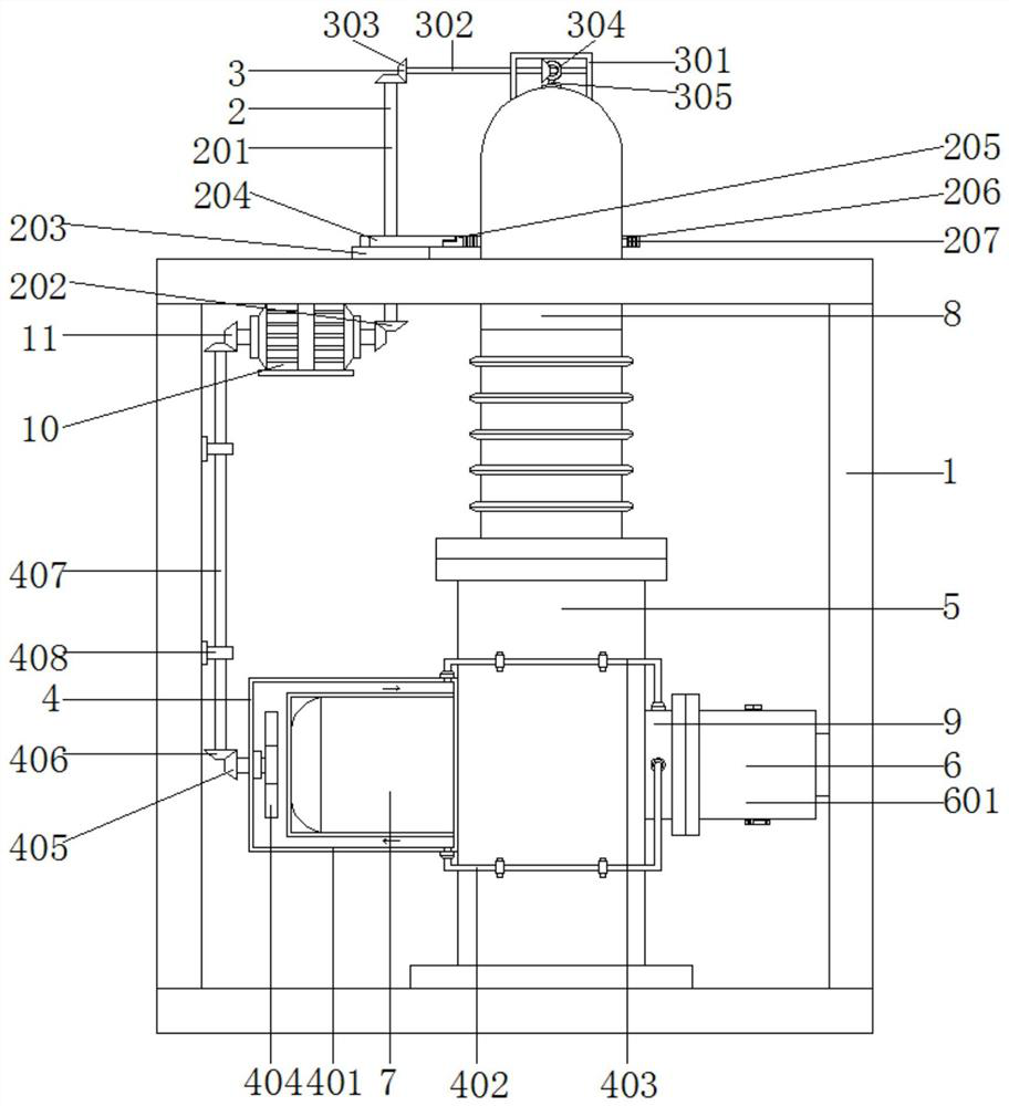
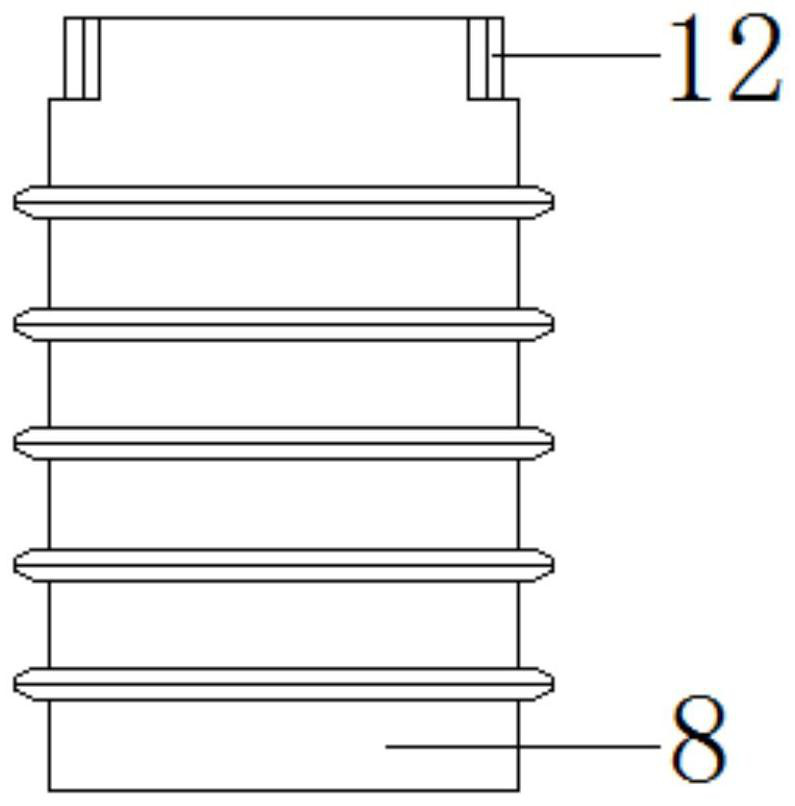
[0046] see Figure 1-4 and Figure 12 , a new type of water pump, comprising a frame 1 and a water pump main body 5, the water pump main body 5 is fixedly connected above the bottom of the frame 1, a driving motor 7 is installed on one side of the water pump main body 5, and a connecting pipe 9 is installed on the other side, the water pump main body 5 The top of the drainpipe 8 is provided with a drainpipe 8, and the bottom end of the drainpipe 8 passes through the top of the frame 1, and a sealed bearing 12 is arranged between the bottom end and the top of the water pump main body 5; 5 between the rotary connections.

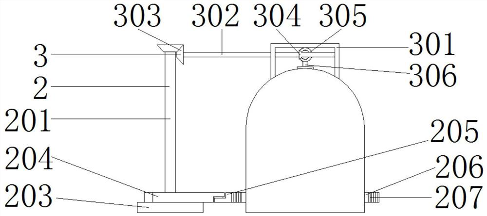
[0047] One side of the drain pipe 8 is provided with a first adjustment mechanism 2, the first adjustment mechanism 2 includes a first transmission rod 201, a first bevel tooth 202, a first gear 203, a movable rod 204, a moving plate 205, and a semicircular tooth pattern. Plate 206, rectangular toothed plate 207, slide plate 208, clip 209 and second gear 210...

Embodiment 2

[0050] see figure 1 , 3 , 5 and Figure 12 , the top of the drain pipe 8 is provided with a second adjustment mechanism 3, the second adjustment mechanism 3 includes a concave plate frame 301, a second transmission rod 302, a second bevel tooth 303, a third bevel tooth 304, a support rod 305, a curved rod 306, connecting rod 307 and blocking sheet 308; the top of the drain pipe 8 is provided with a concave plate frame 301, the inside of the concave plate frame 301 is provided with a second transmission rod 302, and the two ends of the second transmission rod 302 are provided with a second Bevel teeth 303, one side of a set of second bevel teeth 303 is engaged with third bevel teeth 304, one side of the third bevel teeth 304 is provided with a curved rod 306, and the two ends of the curved rod 306 are provided with support rods 305, And the middle end is provided with a connecting rod 307 , one end of the connecting rod 307 is provided with a blocking piece 308 , and one end ...

Embodiment 3

[0055] see figure 1 and Figure 6 , the outside of the drive motor 7 is provided with a water-cooling assembly 4, the water-cooling assembly 4 includes a transparent shell 401, a water inlet hose 402, a water outlet hose 403, a stirring leaf 404, a fourth bevel tooth 405, a fifth bevel tooth 406, a third transmission Rod 407, fixing piece 408 and guide pipe 409; The outside of drive motor 7 is provided with transparent shell 401, and the top of one end of transparent shell 401 is provided with water outlet hose 403, and one end of water outlet hose 403 is connected with the top of connecting pipe 9, transparent The bottom of one end of the housing 401 is provided with a water inlet hose 402, and one end of the water inlet hose 402 is connected to the side wall of the connecting pipe 9, and one end of the water inlet hose 402 is provided with a guide tube 409, and the guide tube 409 is arranged on the connecting pipe 9. Inside the pipe 9 ; the other end of the transparent casi...


PUM


Abstract

The invention discloses a novel water pump, and relates to the field of water pumps. The novel water pump comprises a frame and a water pump body, wherein the water pump body is fixedly connected to the upper part of the bottom of the frame; a driving motor is installed on one side of the water pump body; a connecting pipeline is installed on the other side of the water pump body; a drainage pipe is arranged at the top end of the water pump body; the bottom end of the drainage pipe penetrates through the top of the frame; and a sealing bearing is arranged between the bottom end of the drainage pipe and the top end of the water pump body. According to the novel water pump, the drainage pipe rotates back and forth, so that the drainage pipe can spray at multiple angles, the water pressure of a pipeline opening of the drainage pipe is increased, the distance of the drainage pipe is variable, water flow can be broken from the middle, and the spraying area is enlarged.

Description

Technical field: [0001] The invention relates to the field of water pumps, in particular to a novel water pump. Background technique: [0002] A pump is a machine that transports or pressurizes a liquid. It transmits the mechanical energy of the prime mover or other external energy to the liquid to increase the energy of the liquid. It is mainly used to transport liquids including water, oil, acid and alkali, emulsion, suspoemulsion and liquid metal. [0003] Liquids, gas mixtures and liquids containing suspended solids can also be transported. The technical parameters of pump performance include flow rate, suction lift, lift, shaft power, water power, efficiency, etc.; according to different working principles, it can be divided into volumetric pumps, vane pumps and other types. Positive displacement pumps use the change in the volume of their working chambers to transfer energy; vane pumps use the interaction between rotating blades and water to transfer energy, and ther...

Claims


Application Information

Patent Timeline
Patent Type & Authority Applications(China)
IPC IPC(8): F04B53/16F04B53/08F04B53/20F04B49/08H02K5/20H02K9/19
CPCF04B53/16F04B53/08F04B53/20F04B49/08H02K5/203H02K9/19
Inventor 汪卫平唐子一占洋洋汪渌吴海洋黄文龙李建新
Owner 安徽川子泵阀密封有限公司
Why Eureka
Try Eureka