Parallel beamforming training with coordinated base stations

A beamforming and base station technology, applied in the field of parallel beamforming training with coordinating base stations, can solve problems such as high path loss, difficulty in receiving mmW signals for base stations, and increasing the effective communication range of mmW transmissions

Pending Publication Date: 2021-12-31
GOOGLE LLC
View PDF0 Cites 0 Cited by
  • Summary
  • Abstract
  • Description
  • Claims
  • Application Information

AI Technical Summary

Problems solved by technology

[0002] However, there are various technical challenges associated with the use of mmW signals, such as the higher path loss experienced by mmW signals compared to earlier generation signals
Higher path loss can make it difficult for base stations to receive mmW signals from distant devices
Therefore, there is an opportunity to increase the effective communication range of mmW transmission

Method used


Image

  • Parallel beamforming training with coordinated base stations
  • Parallel beamforming training with coordinated base stations
  • Parallel beamforming training with coordinated base stations

Examples


example 1

[0111] Example 1: A method for a user equipment, the method comprising the user equipment:

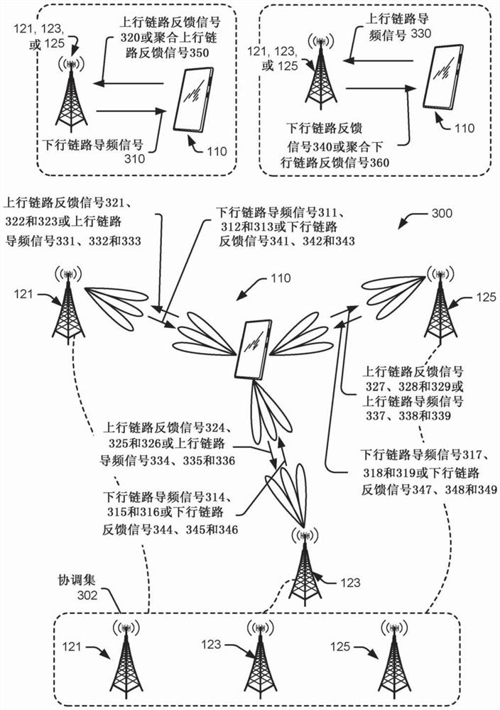
[0112] receiving a first downlink pilot signal from a first base station within the coordinating set;

[0113] generating a first uplink feedback signal based on the first downlink pilot signal;

[0114] receiving a second downlink pilot signal from a second base station within the coordinating set;

[0115] generating a second uplink feedback signal based on the second downlink pilot signal;

[0116] transmitting the first uplink to the first base station in a first pattern that interleaves a first transmission time of the first uplink feedback signal with a second transmission time of the second uplink feedback signal feeding back a signal and sending the second uplink feedback signal to the second base station; and

[0117] performing parallel beamforming training with the first base station and the second base station according to the first pattern.

example 2

[0118] Example 2: The method of Example 1, wherein:

[0119] The first uplink feedback signals respectively correspond to the first downlink pilot signals;

[0120] The second uplink feedback signals respectively correspond to the second downlink pilot signals; and

[0121] The first reception time of the first downlink pilot signal and the second reception time of the second downlink pilot signal are interleaved, wherein the second pattern represents the first downlink The interleaving of the road pilot signal and the second downlink pilot signal,

[0122] The method further comprises:

[0123] The first pattern is determined based on the second pattern such that the first uplink feedback signal is based on the interleaving of the first downlink pilot signal and the second downlink pilot signal with the The second uplink feedback signal is interleaved.

example 3

[0124] Example 3: The method according to Example 2, further comprising:

[0125] receiving a scheduling configuration message from the first base station, the scheduling configuration message specifying a first time delay and a second time delay, wherein:

[0126] a first transmission time of the first uplink feedback signal is interleaved with a first reception time of the first downlink pilot signal based on the first time delay; and

[0127] A second transmission time of the second uplink feedback signal is interleaved with a second reception time of the second downlink pilot signal based on the second time delay.


PUM


Abstract

This document describes techniques and apparatuses for parallel beamforming training with coordinated base stations. In particular, a user equipment (UE) (110) uses time-division multiplexing (TDM) to perform parallel beamforming training with multiple base stations (121, 122, and 123) within a coordination set (302). The TDM interleaves beamforming training signals associated with different base stations. In other words, at least one beamforming training signal associated with a first base station (121) occurs between two beamforming training signals associated with a second base station (123). Example types of beamforming training signals include downlink pilot signals (310), uplink feedback signals (320), uplink pilot signals (330), and downlink feedback signals (340). In some situations, the different types of beamforming training signals are further interleaved together based on expected rates at which channel conditions change. By interleaving beamforming training signals, narrow beams can be formed to support millimeter-wave (mmW) communications at cell edges.

Description

Background technique [0001] Cellular and other wireless networks are able to increase transmission for newer generations of wireless communications, such as fifth generation new radio (5GNR), by using signals with higher frequencies and shorter wavelengths relative to signals used for earlier generations of wireless communications rate and throughput. These signals can have frequencies at or near the extremely high frequency (EHF) spectrum (eg, frequencies greater than 24 gigahertz (GHz)) at wavelengths at or near one to ten millimeters (mmW). [0002] However, there are various technical challenges associated with using mmW signals, such as the higher path loss experienced by mmW signals compared to earlier generation signals. Higher path loss can make it difficult for base stations to receive mmW signals from distant devices. Therefore, there is an opportunity to increase the effective communication range of mmW transmission. Contents of the invention [0003] Technique...

Claims


Application Information

Patent Timeline
IPC IPC(8): H04B7/024H04B7/06H04B7/08
CPCH04B7/024H04B7/0695H04B7/088H04B7/0617H04L1/0071H04L5/0048H04L5/0055
Inventor 王继兵埃里克·理查德·施陶费尔
Owner GOOGLE LLC
Why Eureka
Try Eureka