Eureka AIR delivers breakthrough ideas for toughest innovation challenges, trusted by R&D personnel around the world.

Circumferential locking device and circumferential locking method of traction system

A locking device and traction system technology, which is applied in the field of locking devices, can solve problems such as damage to the traction shaft, deflection of the traction shaft, and insufficient damping, and achieve the effects of increasing the contact area, increasing damping, and reducing pressure

Pending Publication Date: 2022-01-04
SHANGHAI ELECTRICGROUP CORP
View PDF0 Cites 0 Cited by
  • Summary
  • Abstract
  • Description
  • Claims
  • Application Information

AI Technical Summary

Problems solved by technology

[0003] The technical problem to be solved by the present invention is to overcome the defects in the prior art that the traction shaft is easily damaged during the locking process, and the damping after locking is not enough, and the traction shaft is prone to deflection after locking, and provides a peripheral Circumferential locking method of locking device and traction system

Method used


Image

  • Circumferential locking device and circumferential locking method of traction system
  • Circumferential locking device and circumferential locking method of traction system
  • Circumferential locking device and circumferential locking method of traction system

Examples


Embodiment Construction

[0070] The present invention is further illustrated below by means of examples, but the present invention is not limited thereto within the scope of examples.

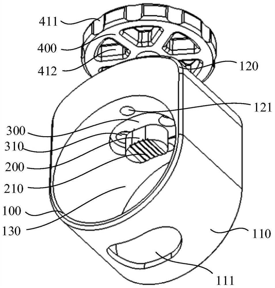
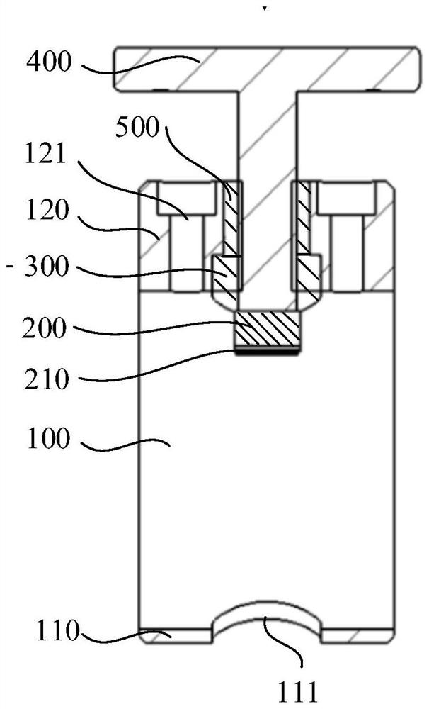
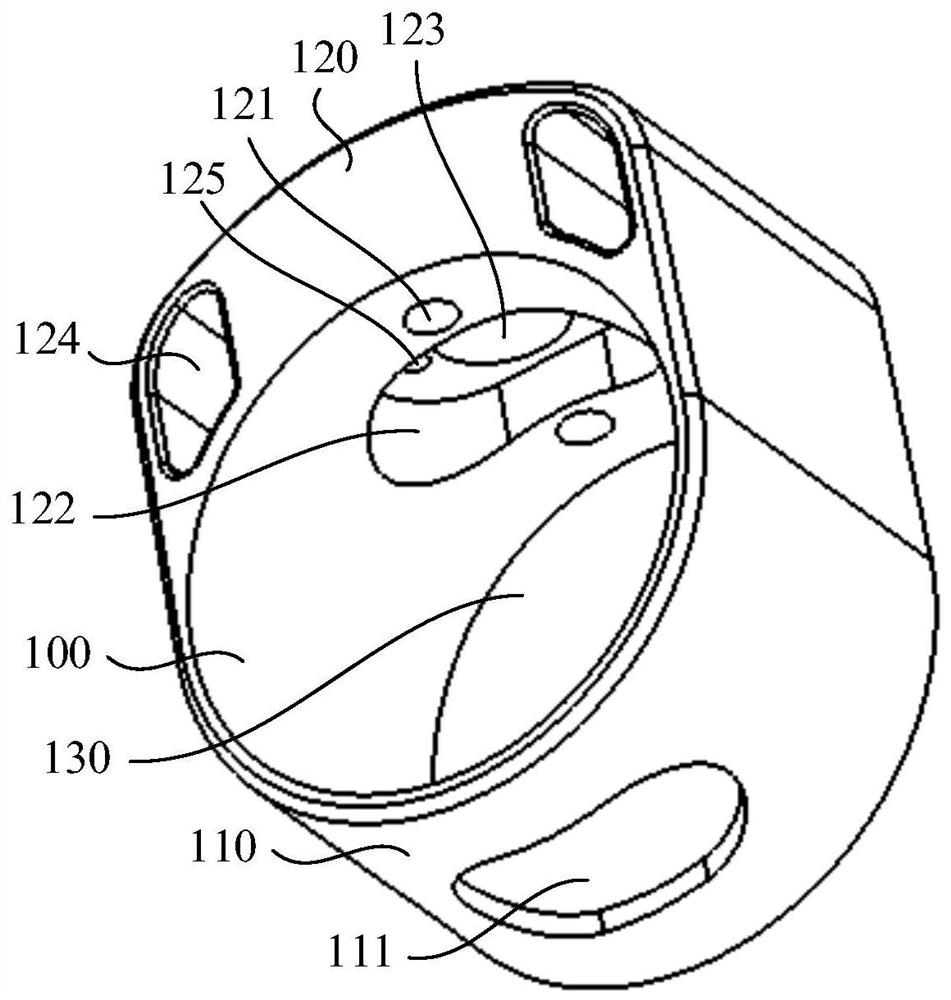
[0071] In this example, if Figure 1-7 As shown, a circumferential locking device includes:

[0072] Base 100,

[0073] The briquetting block 200, the lower end surface of the briquetting block 200 is a curved surface, the lower end surface is used to fit the traction shaft 700, and the surface hardness of the briquetting block 200 is greater than that of the traction shaft 700;

[0074] A locking device, the locking device is installed on the base 100 , the locking device is connected to the pressing block 200 , and the locking device drives the pressing block 200 close to or away from the traction shaft 700 .

[0075] Wherein, the appearance of the pressing block 200 is in the shape of a waist-shaped cylinder, and the surface in contact with the traction shaft 700 is a curved surface. The locking device is install...


PUM


Abstract

The invention discloses a circumferential locking device and a circumferential locking method of a traction system, and relates to the field of locking devices. The circumferential locking device comprises a base, a pressing block and a locking device body, wherein the lower end face of the pressing block is a curved surface, the first end face is tightly attached to a traction shaft, and the surface hardness of the pressing block is larger than that of the traction shaft; the locking device body is installed on the base; the locking device body is connected to the pressing block, the locking device body drives the pressing block to be close to or away from the traction shaft; a containing cavity is formed in the side end face of the base; and the base is provided with a locking hole communicated with the containing cavity. According to the scheme, the pressing block is adopted as a middle body, the curved surface end of the pressing block is tightly attached to the traction shaft, and after the traction shaft is locked through the locking device body, the contact area between the pressing block and the traction shaft can be increased, damping after locking can be increased, the pressure intensity on the traction shaft can be reduced, and the traction shaft is not prone to being damaged.

Description

technical field [0001] The invention relates to the field of locking devices, in particular to a circumferential locking device and a circumferential locking method of a traction system. Background technique [0002] In total hip replacement surgery, the traction system is required to guide and support the patient's leg. Among them, there is a function in the traction system that can rotate the patient's leg around the axis by a corresponding angle. After the adjustment is completed, the traction shaft needs to be locked and fixed. The existing circumferential locking device usually locks the traction shaft by screwing. Because the strength of the traction shaft is low, it is easy to cause damage to the traction shaft during the locking process, and the damping after locking is not enough. The traction shaft is prone to deflection after locking. Contents of the invention [0003] The technical problem to be solved by the present invention is to overcome the defects in the...

Claims


Application Information

Patent Timeline
Patent Type & Authority Applications(China)
IPC IPC(8): A61G13/12
CPCA61G13/1245
Inventor 付亚波叶震张长青赵志浩
Owner SHANGHAI ELECTRICGROUP CORP
Why Eureka
Eureka Blog
Learn More