Chip collecting device for milling and turning combined machine tool

A technology of collecting device and compound machine tool, which is applied in metal processing machinery parts, maintenance and safety accessories, metal processing equipment, etc. Practical value, avoid chip accumulation, avoid scattered effect

Pending Publication Date: 2022-01-04
湖南九五精机有限责任公司
View PDF6 Cites 0 Cited by
  • Summary
  • Abstract
  • Description
  • Claims
  • Application Information

AI Technical Summary

Problems solved by technology

[0003] At present, when most of the metals in the market are cutting, the metal debris that breaks and falls off during the cutting is attached to the surface of the milling cutter. If it is not cleaned in time, it will increase the burden on the milling cutter, and the chips and debris generated generally fall directly on the milling cutter. There is no collection device on the surface of the car, and the debris is scattered everywhere. After it is completed, manual hands need to be inserted into the interior of the equipment for cleaning. If the equipment is not closed during manual cleaning, it is likely to pose a threat to the life safety of the staff, and manual cleaning is very difficult. Troublesome, inefficient and not clean, therefore, a chip collection device for milling and turning compound machine tools is proposed to solve the above problems

Method used


Image

  • Chip collecting device for milling and turning combined machine tool
  • Chip collecting device for milling and turning combined machine tool
  • Chip collecting device for milling and turning combined machine tool

Examples


Embodiment 1

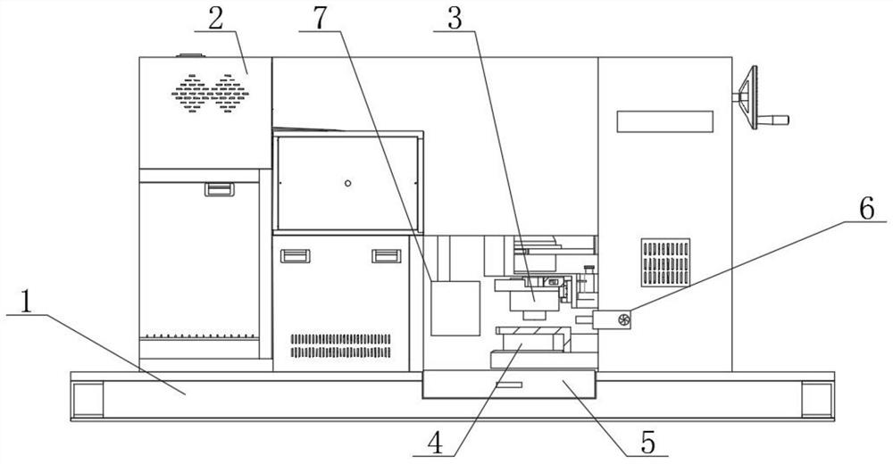
[0027] see figure 1 , figure 2 , image 3 , Figure 4 , Figure 5 , Figure 6 and Figure 7 , the present invention provides a technical solution:

[0028]A chip collection device for a milling-turning compound machine tool, comprising a base 1 and a milling machine 2, the upper end of the base 1 is fixedly connected to the milling machine 2, the inside of the milling machine 2 is fixedly connected to a milling cutter 3, and a fixed table 4 is provided below the milling cutter 3, and the fixed table 4. The right side is fixedly connected with the milling machine 2. The right side of the milling cutter 3 is provided with a blowing mechanism 6. The blowing mechanism 6 includes a fixed box 601 and a fan 602. The outside of the fixed box 601 is fixedly connected with the milling machine 2. The inside of the fixed box 601 is fixedly connected with Fan 602, the fan 602 provides wind power to make the chips blow to the left, the left side of the fan 602 is fixedly connected wi...

Embodiment 2

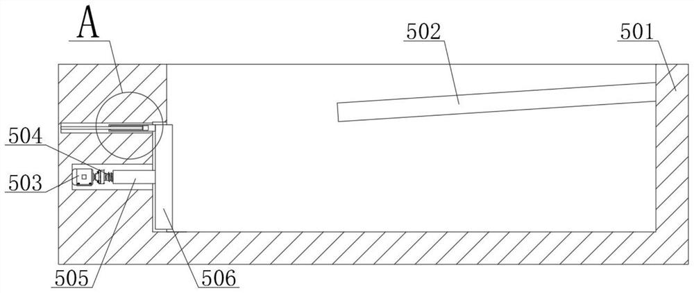
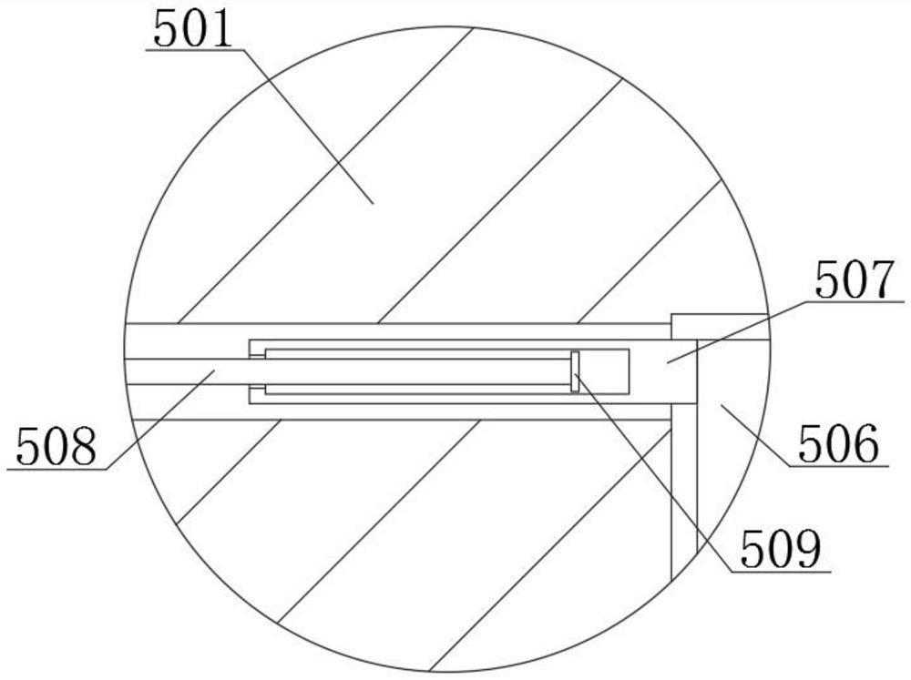
[0031] In Embodiment 2, the same parts as in Embodiment 1 will not be described again. The difference is that the setting of the inclined net 502 ensures that the chips falling from the fixed table 4 enter the sliding frame 501, and prevent the chips pushed to the right from falling out of the sliding frame. 501 overflows to ensure that the chips can be compressed and expand its capacity. When it needs to process the chips, slide the sliding frame 501 at this time, and then the chips can be processed centrally, saving a lot of time and improving cleaning efficiency.


PUM


Abstract

The invention relates to the technical field of milling and turning compound machines, in particular to a chip collecting device for a milling and turning combined machine tool. The chip collecting device comprises a base and a milling machine, wherein the upper end face of the base is fixedly connected with the milling machine, the milling machine is internally and fixedly connected with a milling cutter, a fixed table is arranged below the milling cutter, the right side of the fixed table is fixedly connected with the milling machine, a blowing mechanism is arranged on the right side of the milling cutter, the outer side of the blowing mechanism is fixedly connected with the milling machine, a collecting device is arranged below the fixed table, and the outer side of the collecting device is slidably connected with the base. According to the device, a sliding frame, a push plate and a sliding plate are arranged, the sliding frame can collect chips, the push plate can push the chips towards the right side to avoid accumulation of the chips, and the sliding plate and the fixed plate can prevent the chips from being located on the left side of the push plate, the chips can only move rightwards to be compressed, the storage amount of the sliding frame is guaranteed, and an inclined net is arranged, so that the chips can fall down.

Description

technical field [0001] The invention relates to the technical field of milling and turning compound machines, in particular to a chip collecting device for milling and turning compound machine tools. Background technique [0002] A milling machine is a machine tool with a wide range of uses. It can process planes (horizontal planes, vertical planes), grooves (key slots, T-shaped slots, dovetail slots, etc.), toothed parts (gears, spline shafts, sprockets), Spiral surface (thread, spiral groove) and various curved surfaces. In addition, it can also be used to process and cut off the surface and inner hole of the rotary body. When the milling machine is working, the workpiece is installed on the workbench or on the accessories such as the dividing head. , the rotation of the milling cutter is the main movement, supplemented by the feed movement of the table or the milling head, the workpiece can obtain the required processing surface, because it is multi-blade intermittent cut...

Claims


Application Information

Patent Timeline
Patent Type & Authority Applications(China)
IPC IPC(8): B23Q11/00
CPCB23Q11/0042B23Q11/0064B23Q11/0067
Inventor 吴向忠高明铭冉晓茹李军舰朱坤郝军平彭晓云谭幸运朱宏杰
Owner 湖南九五精机有限责任公司
Why Eureka
Try Eureka