Single-acting clamping jig with shearing function

A technology of dynamic clamping and fixtures, which is applied in the field of single-action clamping fixtures, can solve problems such as shortening the injection molding cycle and rod deformation, and achieve the effects of shortening the injection molding cycle, low cost, and reliable clamping

Pending Publication Date: 2022-01-04
NINGBO BEILONG PRECISION MOLDING
View PDF5 Cites 0 Cited by
  • Summary
  • Abstract
  • Description
  • Claims
  • Application Information

AI Technical Summary

Problems solved by technology

[0004] The present invention provides a single-action clamping fixture with a shearing function in order to overcome the disadvantages of clamping the injection molded product before it is completely cooled and shaped, and the possible interference with the punch of the punching machine caused by the deformat

Method used


Image

  • Single-acting clamping jig with shearing function
  • Single-acting clamping jig with shearing function
  • Single-acting clamping jig with shearing function

Examples


Embodiment 1

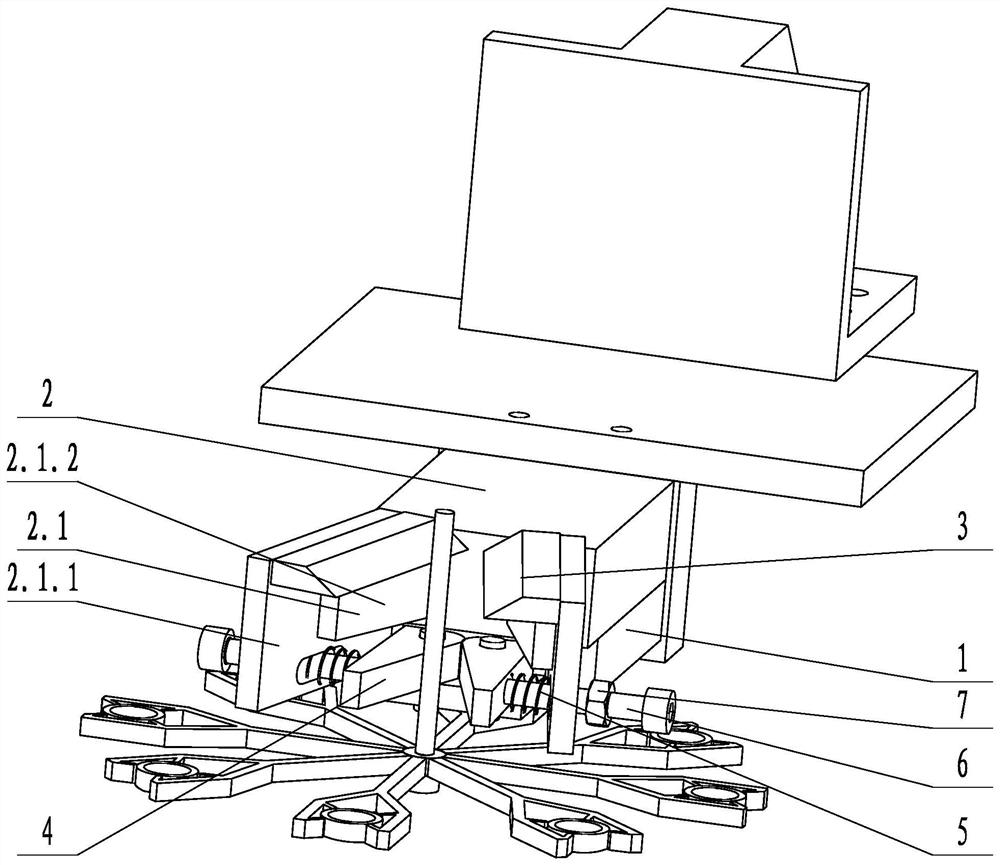
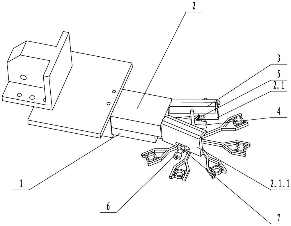
[0023] Such as figure 1 and figure 2 As shown, a single-action clamping fixture with shearing function includes a connecting plate 1, a jaw cylinder 2, two shearing blades 3, two clamping plates 4, two telescopic springs 5 ​​and two The guide rod 6, the shearing blade 3 is set above the clamping plate 4, the clamping jaw cylinder 2 is fixed to the connecting plate 1, the clamping jaw cylinder 2 includes two clamping jaw moving pieces 2.1, and the shearing blade 3 and the clamping corresponding claws move The plate is fixed, the clamping plate 4 is connected to the connecting plate 1 in rotation, one end of the telescopic spring 5 is connected to the corresponding jaw moving piece 2.1, the other end of the telescopic spring 5 is connected to the corresponding clamping plate 4, and one end of the guide rod 6 is connected to the clip The tight plate 4 is fixed, the other end of the guide rod 6 passes through the jaw movable piece 2.1, and the telescopic spring 5 is sleeved on t...

Embodiment 2

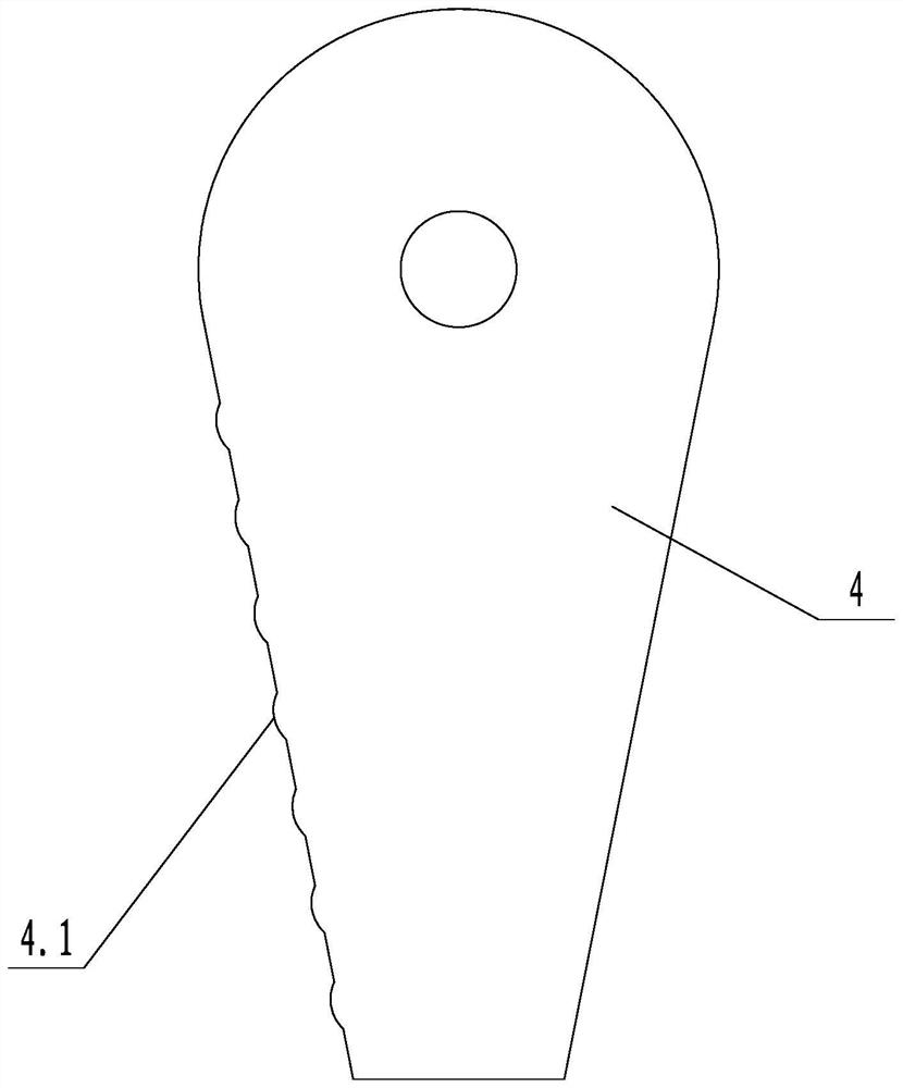
[0026] Such as image 3 As shown, on the basis of Embodiment 1, the connecting moving piece 2.1.1 is vertically provided with a long groove, and the clamping plate 4 is fixed to the connecting moving piece 2.1.1 through the long groove and bolts. The side wall of the clamping plate 4 is provided with a plurality of vertical positioning convex strips 4.1, and several positioning convex strips 4.1 are arranged at intervals. The edges of the two shearing blades 3 are staggered and arranged in close contact with each other. The cutting edges of the shearing blades 3 are staggered and close to each other so that the cutting effect of the two shearing blades 3 is better, and the two shearing blades 3 form a scissors effect. The positioning convex strip 4.1 can prevent the material rod from sliding relative to the clamping plate 4 when the clamping plate 4 clamps the product material rod, so that the clamping position is more accurate and the clamping is more reliable.

[0027] The...


PUM


Abstract

The invention discloses a single-acting clamping jig with a shearing function. The single-acting clamping comprises a connecting plate, a clamping jaw air cylinder, a shearing blade, a clamping plate and a stretchable spring, the shearing blade is arranged above the clamping plate, the clamping jaw air cylinder is fixed to the connecting plate, the clamping jaw air cylinder comprises a clamping jaw moving piece, the shearing blade is fixed to the clamping jaw moving piece, the clamping plate is rotationally connected with the connecting plate, one end of the stretchable spring is connected with the clamping jaw moving piece, and the other end of the stretchable spring is connected with the clamping plate. According to the single-acting clamping jig with the shearing function, a material rod of an injection molding product is cut to be short, so that possible interference between the material rod and a punch of a punching machine caused by deformation of the material rod is avoided, and further shortening of the injection molding period becomes reality; and two actions of clamping and shearing of the product can be completed through one clamping jaw air cylinder, the structure is more compact, the cost is lower, and clamping and shearing are more reliable.

Description

technical field [0001] The invention relates to the technical field of reclaiming jigs, in particular to a single-action clamping jig with a shearing function. Background technique [0002] The injection molding industry is a highly competitive industry, and the injection molding cycle is one of the most important parameters for cost control and production capacity control. If you can effectively reduce the injection molding cycle, you can win a competitive advantage. At present, the traditional method of reducing the cycle time does not involve the jig for taking the material. Generally, the mold is opened and clamped after the injection molded part is cooled. This method needs to wait for the product to be completely cooled and shaped before clamping, which cannot reduce the injection molding cycle to the greatest extent. If the product is clamped before it is completely cooled and shaped, the upper section of the material rod of the product will be deformed during clampi...

Claims


Application Information

Patent Timeline
IPC IPC(8): B29C45/38B29C45/42
CPCB29C45/382B29C45/4225
Inventor 李振锋
Owner NINGBO BEILONG PRECISION MOLDING
Why Eureka
Try Eureka