A slidable platform canopy decoration construction operation platform and construction method
A technology for operating platforms and canopies, used in construction, scaffolding accessories, housing structure support, etc., can solve the problem of not being able to carry out coating construction on the top wall and platform floor at the same time, to ensure stability, save erection costs, and avoid damage. Effect
- Summary
- Abstract
- Description
- Claims
- Application Information
AI Technical Summary
Problems solved by technology
Method used
Image
Examples
Embodiment 1
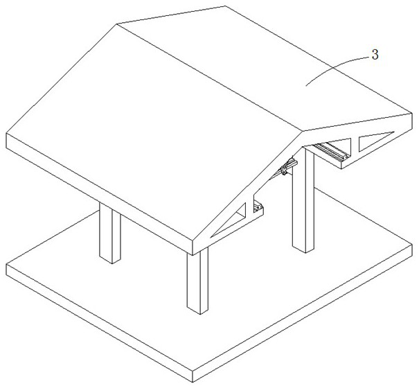
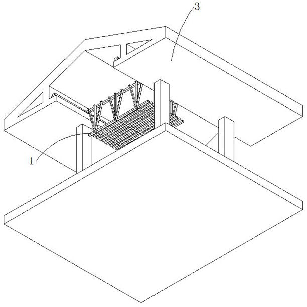
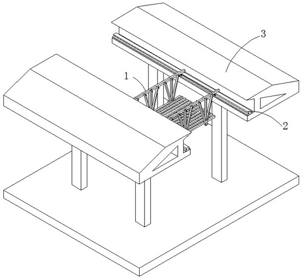
[0037] refer to Figure 1-9 , a slidable platform canopy decoration construction operation platform, including a frame body 1 and a slide rail 2, the slide rail 2 is fixedly connected to the canopy 3, the frame body 1 is slidably connected to the slide rail 2, and the slide rail 2 is set There is a guide groove 4, the frame body 1 is fixedly connected with a connecting shaft 6, and the lower end of the connecting shaft 6 is rotatably connected with a guide wheel 5;
[0038] A pressure groove 7 is opened on the slide rail 2, and a bead 8 is slidably connected to the bead 8 on the bead 7. Rod 13, the bottom side of the guide wheel 5 is provided with a stable slot 12 corresponding to the insertion rod 13, a drive cylinder 14 is fixedly connected to the slide rail 2, and a piston rod 15 is slidably connected to the drive cylinder 14, and the piston rod 15 is fixed to the insertion rod 13 The airbag 10 is connected with the driving tube 14 through the ventilation pipe 11; when it ...
Embodiment 2
[0041] refer to Figure 1-9 , a slidable platform canopy decoration construction operation platform, including a frame body 1 and a slide rail 2, the slide rail 2 is fixedly connected to the canopy 3, the frame body 1 is slidably connected to the slide rail 2, and the slide rail 2 is set There is a guide groove 4, the frame body 1 is fixedly connected with a connecting shaft 6, and the lower end of the connecting shaft 6 is rotatably connected with a guide wheel 5;
[0042]A pressure groove 7 is opened on the slide rail 2, and a bead 8 is slidably connected to the bead 8 on the bead 7. Rod 13, the bottom side of the guide wheel 5 is provided with a stable slot 12 corresponding to the insertion rod 13, a drive cylinder 14 is fixedly connected to the slide rail 2, and a piston rod 15 is slidably connected to the drive cylinder 14, and the piston rod 15 is fixed to the insertion rod 13 The airbag 10 is connected with the driving tube 14 through the ventilation pipe 11; when it i...
Embodiment 3
[0047] refer to Figure 1-9 , is basically the same as that of Embodiment 2, and furthermore, the number of inclined clamping plates 17 is 2-4, and they are evenly distributed on the stable plate 16 to improve the stability.
[0048] The upper side of the inclined clamping plate 17 is arc-shaped, and the side of the clamping rod 20 close to the inclined clamping plate 17 is arc-shaped, so that the clamping rod 20 can be snapped into the inclined clamping plate 17 from above.
[0049] A back-moving spring 9 is arranged in the pressure groove 7, and the two ends of the back-moving spring 9 are respectively connected to the bottom wall of the pressure groove 7 and the bead 8, so as to facilitate the upward movement and reset of the bead 8.
[0050] The stabilizing plate 16 and the slide rail 2 are all connected on the canopy 3 by fixing bolts, and are fixedly connected.
PUM
 Abstract
Description
Claims
Application Information
 - R&D
- Intellectual Property
- Life Sciences
- Materials
- Tech Scout
- Unparalleled Data Quality
- Higher Quality Content
- 60% Fewer Hallucinations
Browse by: Latest US Patents, China's latest patents, Technical Efficacy Thesaurus, Application Domain, Technology Topic, Popular Technical Reports.
© 2025 PatSnap. All rights reserved.Legal|Privacy policy|Modern Slavery Act Transparency Statement|Sitemap|About US| Contact US: help@patsnap.com


