Ventilation equipment convenient to disassemble and assemble

A kind of ventilation equipment and convenient technology, which is used in the ventilation of mines/tunnels, mining equipment, and earth-moving drilling, etc. It can solve the problems of difficulty in disassembly and assembly of ventilation equipment, difficult to adjust the angle, etc., to broaden the scope of application and practicality, and to facilitate disassembly , Improve the effect of disassembly efficiency

Inactive Publication Date: 2022-01-04
重庆黄牛通风设备有限公司
View PDF0 Cites 0 Cited by
  • Summary
  • Abstract
  • Description
  • Claims
  • Application Information

AI Technical Summary

Problems solved by technology

[0003] The purpose of the present invention is to at least solve one of the technical problems in the prior art, to provide a ventilator that is easy to disassemble and assemble, and can solve the problems that the ventilator is difficult to disassemble and the angle is difficult to adjust

Method used


Image

  • Ventilation equipment convenient to disassemble and assemble
  • Ventilation equipment convenient to disassemble and assemble
  • Ventilation equipment convenient to disassemble and assemble

Examples


Embodiment 1

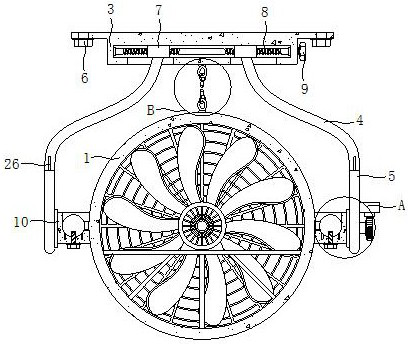
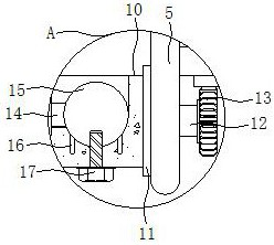
[0027] see Figure 1-5 , the present invention provides a technical solution: a convenient disassembly and assembly ventilation equipment, including a jet fan 1, a horizontal frame plate 3, a disassembly mechanism and an adjustment mechanism, the horizontal frame plate 3 is arranged on the top of the jet flow fan 1, and the horizontal frame plate The bottom of 3 is provided with two sets of vertical boards 5, and the vertical boards 5 are provided with connecting blocks 10, and the tops of the two groups of connecting blocks 10 are provided with T-shaped slots, and the front and rear side outer walls of the jet fan 1 are provided with positioning columns 15 for positioning. The column 15 is located in the T-shaped slot. The dismounting mechanism includes a slider 7, a two-way screw rod 8 and a hexagonal block 9 arranged on the horizontal frame plate 3. The dismounting mechanism can drive the two sets of connecting blocks 10 to move in the same direction or in the opposite direc...

Embodiment 2

[0032] see Figure 1-5 , on the basis of Embodiment 1, a positioning rod 16 is fixedly installed at the bottom of the positioning column 15, and the positioning rod 16 is clamped and installed in the positioning perforation. slot, the bottom of the connection block 10 is provided with a positioning bolt 17, the positioning bolt 17 passes through the opening and extends into the threaded groove, the connecting nut 6 on the horizontal frame plate 3 is screwed on the bolt at the pre-embedded position, and then the The horizontal frame plate 3 is installed, and then the jet fan 1 is hoisted between the two sets of vertical plates 5 under the horizontal frame plate 3, and then the hexagonal block 9 is twisted by holding the paste, and the hexagonal block 9 drives the rotation of the two-way screw rod 8 and drives Two groups of sliders 7 move in the same direction, and the two groups of sliders 7 drive two groups of connecting curved rods 4, two groups of vertical plates 5 and two g...


PUM


Abstract

The invention discloses ventilation equipment convenient to disassemble and assemble, and relates to the technical field of tunnel ventilation. The ventilation equipment convenient to disassemble and assemble comprises a jet fan, a transverse frame plate, a disassembling and assembling mechanism and an adjusting mechanism, the transverse frame plate is arranged at the top of the jet fan, two sets of vertical plates are arranged at the bottom of the transverse frame plate, two sets of connecting blocks are arranged on the vertical plates, and T-shaped grooves are formed in the tops of the two sets of connecting blocks. According to the ventilation equipment convenient to disassemble and assemble, the jet fan can be rapidly assembled or disassembled, the complexity that after the jet fan is lifted, hole alignment operation needs to be conducted, and a plurality of sets of bolts need to be installed is avoided, the installation efficiency of the equipment is improved, and disassembly is convenient. Compared with the mode that disassembly operation is completed by disassembling the multiple sets of bolts, the disassembly efficiency is remarkably improved, the angle of the jet fan can be conveniently adjusted, the position of an air port of the jet fan can be conveniently and automatically adjusted when encountering a large shielding object, and the use reliability of the equipment is ensured.

Description

technical field [0001] The invention relates to the technical field of tunnel ventilation, in particular to a conveniently disassembled and assembled ventilation device. Background technique [0002] The jet fan is one of the ventilation equipment. Generally, it plays the role of inducing air flow or exhausting smoke at the inlet and outlet during tunnel installation. It plays an important role in tunnel ventilation. Some of the existing jet fans are installed by lifting The equipment lifts it, aligns the holes with the embedded bolts and uses nuts to complete the installation, but the process of aligning the holes will waste a lot of time, and the jet fan needs to be disassembled and assembled during subsequent maintenance, and then multiple sets of nuts need to be loosened. Indirectly, it is difficult to disassemble and assemble the ventilation equipment, and it is inconvenient to adjust the angle after the jet fan is installed. Once obstacles appear on the side of the pre...

Claims


Application Information

Patent Timeline
Patent Type & Authority Applications(China)
IPC IPC(8): E21F1/08
CPCE21F1/08
Inventor 黄良建刘福丽
Owner 重庆黄牛通风设备有限公司
Why Eureka
Try Eureka