Variable diffuser structure of centrifugal machine and centrifugal machine

A diffuser and centrifuge technology, applied in the field of centrifuges, can solve the problems such as the small gas flow adjustment range of the centrifugal compressor and the easy entry of the centrifuge into the surge.

Pending Publication Date: 2022-01-04
钛灵特压缩机无锡有限公司
View PDF7 Cites 0 Cited by
  • Summary
  • Abstract
  • Description
  • Claims
  • Application Information

AI Technical Summary

Problems solved by technology

[0004] Therefore, the present invention aims to solve the technical problem that the gas flow adjustment range of the centrifugal compressor is small, and the centrifuge is easy to enter the surge, thereby providing a variable diffuser structure of the centrifuge and a centrifuge

Method used


Image

  • Variable diffuser structure of centrifugal machine and centrifugal machine
  • Variable diffuser structure of centrifugal machine and centrifugal machine
  • Variable diffuser structure of centrifugal machine and centrifugal machine

Examples


Embodiment

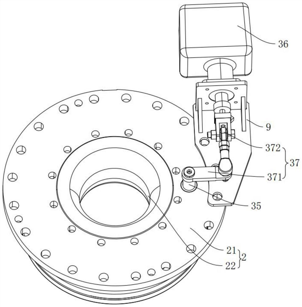
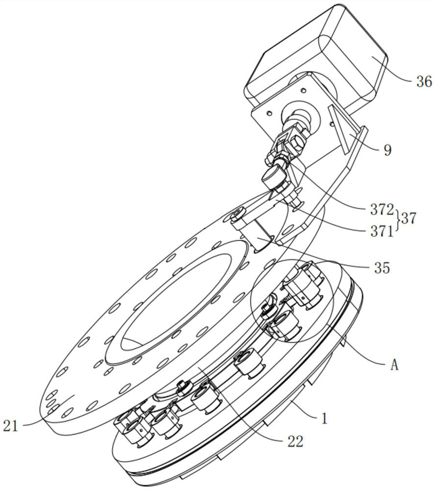
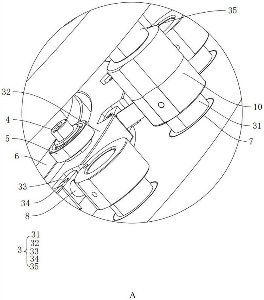
[0038] refer to Figure 1-Figure 4 As shown, the present invention provides a centrifuge, including a variable diffuser structure of the centrifuge, and the variable diffuser structure of the centrifuge includes a deflector 2, a plurality of diffuser blades 1 and a connecting rod driver 3; A plurality of diffuser blades 1 are evenly arranged in a ring on one side of the guide body 2, and are rotatably connected with the guide body 2; the connecting rod driver 3 is used to simultaneously drive the plurality of diffuser blades 1 to rotate in the same direction.

[0039] When in use, multiple diffuser blades 1 are driven to rotate in the same direction through the connecting rod driver 3, so that multiple diffuser blades 1 can be rotated and switched synchronously at the same time to achieve the purpose of adjusting the flow area of ​​the exhaust port. Then, in cooperation with the guide vane mechanism, the two mechanisms are driven by the actuator 36 at the same time, so that th...


PUM


Abstract

The invention relates to a variable diffuser structure of a centrifugal machine and the centrifugal machine. The variable diffuser structure of the centrifugal machine comprises a flow guide body, a plurality of diffuser blades and a connecting rod driver. The diffuser blades are annularly arranged on one side of the flow guide body and rotationally connected with the flow guide body. The connecting rod driver is used for simultaneously driving the multiple diffuser blades to rotate in the same direction. The variable diffuser structure of the centrifugal machine has the effects that the surge area of the centrifugal compressor is widened, the centrifugal compressor can operate under the working condition of 40%-100%, the surge area is enlarged, the adaptability of the centrifugal compressor is wider, the application requirements of customers under partial loads are met, and the requirement of stable operation of the centrifugal compressor is met.

Description

technical field [0001] The invention relates to the technical field of centrifuges, in particular to a variable diffuser structure of a centrifuge and the centrifuge. Background technique [0002] Centrifugal fans are important process equipment for providing gas power in industrial production, and are widely used in many important industries such as steel, cement, electric power, coal mines, petrochemicals, and waste gas and sewage treatment. The working principle of the centrifugal fan is that the gas is sucked through the center of the impeller through the action of centrifugal force, and then flows into the blades, and then flows out. [0003] In the prior art, conventional centrifugal units use fixed blades to convert the gas flow at the outlet of the impeller into a pressure increase, and only guide the blades at the inlet of the centrifuge to adjust the gas flow, but in this case , The gas flow adjustment range of the centrifugal compressor is small, generally only 7...

Claims


Application Information

Patent Timeline
Patent Type & Authority Applications(China)
IPC IPC(8): F04D29/44F04D29/46F04D27/02
CPCF04D29/444F04D29/462F04D27/0246
Inventor 郭中纬
Owner 钛灵特压缩机无锡有限公司
Why Eureka
Try Eureka