
Friction damper device

A technology for friction dampers and friction parts, which is applied in the direction of friction dampers, shock absorbers, shock absorbers, etc., and can solve the problems of small displacement stroke, increased volume, and increased number of friction dampers

Pending Publication Date: 2022-01-04
GUANGDONG PROVINCE COMM PLANNING & DESIGN INST
View PDF0 Cites 0 Cited by
  • Summary
  • Abstract
  • Description
  • Claims
  • Application Information

AI Technical Summary

Problems solved by technology

However, the common friction dampers at this stage have the problems of small displacement stroke and low energy consumption efficiency. The small displacement stroke will limit the application of friction dampers in engineering structures, such as the longitudinal direction of long-span bridges with large temperature deformation Vibration damping control, etc.; in order to consume more energy, the number of friction dampers has to be increased or the volume increased, which will also increase the difficulty of its application

Method used


Image

  • Friction damper device
  • Friction damper device
  • Friction damper device

Examples


Embodiment Construction

[0023] In order to make the above objects, features and advantages of the present invention more comprehensible, specific implementations of the present invention will be described in detail below in conjunction with the accompanying drawings. In the following description, numerous specific details are set forth in order to provide a thorough understanding of the present invention. However, the present invention can be implemented in many other ways different from those described here, and those skilled in the art can make similar improvements without departing from the connotation of the present invention, so the present invention is not limited by the specific embodiments disclosed below.

[0024] In describing the present invention, it should be understood that the terms "center", "longitudinal", "transverse", "length", "width", "thickness", "upper", "lower", "front", " Back", "Left", "Right", "Vertical", "Horizontal", "Top", "Bottom", "Inner", "Outer", "Clockwise", "Counte...


PUM


Abstract

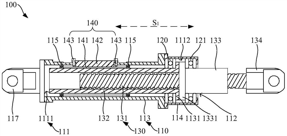
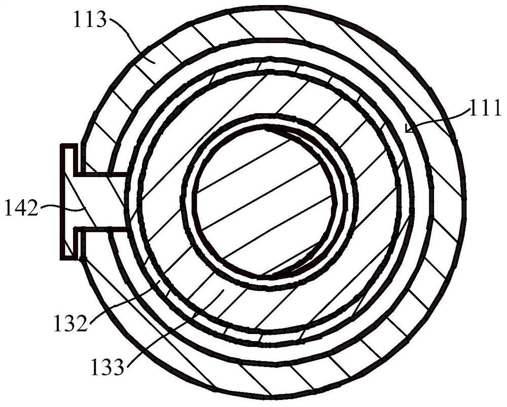
The invention relates to a friction damper device which comprises an outer cylinder assembly, a first rotating piece, a linear rotating assembly and a friction assembly, the outer cylinder assembly is provided with a rotating cavity and a rotating hole, and the rotating hole is communicated with the rotating cavity; the first rotating piece is arranged on the inner wall of the rotating cavity; the linear rotating assembly comprises a lead screw, an inner cylinder and a nut, the inner cylinder is connected with the nut, the lead screw is in threaded connection with the nut, and the inner cylinder is rotationally matched with the first rotating piece; and the friction assembly is arranged on the inner wall of the rotating cavity and is in friction fit with the inner cylinder. According to the friction damper device, linear displacement of the lead screw is converted into rotation of the nut, and the allowable stroke in the energy consumption process can be increased. Besides, on one hand, friction can be generated when the nut and the lead screw are in threaded connection, part of kinetic energy is consumed, meanwhile, the friction assembly generates damping for rotation of the inner cylinder, and then the energy consumption efficiency of the friction damper device is effectively improved.

Description

technical field [0001] The invention relates to the technical field of structural engineering, in particular to a friction damper device. Background technique [0002] Under the strong impetus of economic prosperity and development, the scale and technical level of buildings and bridge construction have to be greatly improved. However, under the influence of natural disasters such as typhoons and earthquakes, building structures suffer from earthquakes and wind disasters, and personal and property losses occur from time to time. Therefore, more and more engineering structures adopt the method of installing energy dissipation and vibration reduction devices to resist the impact of dynamic loads such as earthquakes and typhoons. [0003] Traditionally, dampers have been used to dissipate the dynamic loads of large buildings. The energy dissipation mechanism of the friction damper is that when the two frictional contact surfaces slide relative to each other, there will always...

Claims


Application Information

Patent Timeline
Patent Type & Authority Applications(China)
IPC IPC(8): F16F7/02F16F7/04
CPCF16F7/02F16F7/04F16F7/023
Inventor 梁龙腾柳春
Owner GUANGDONG PROVINCE COMM PLANNING & DESIGN INST
Learn More