Distance measurement compensation device

A compensating device and a technology for adjusting components, which is applied in the field of sights, and can solve problems such as inconvenient operation and carrying, and many scales on the adjustment cover.

Pending Publication Date: 2022-01-04
SINTAI OPTICAL SHENZHEN CO LTD +1
View PDF4 Cites 0 Cited by
  • Summary
  • Abstract
  • Description
  • Claims
  • Application Information

AI Technical Summary

Problems solved by technology

[0004] Since the zero setting must be completed with hand tools, it is not convenient for operation and portability
On the other hand, today's adjustment cover requires a small size but many scales, resulting in a finer structure of the correction mechanism, which is a big challenge to the existing machining technology

Method used


Image

  • Distance measurement compensation device
  • Distance measurement compensation device
  • Distance measurement compensation device

Examples


Embodiment Construction

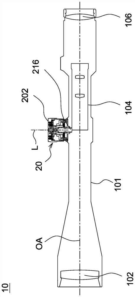
[0023] see figure 1 The distance measuring compensation device of the present invention is further a collimator 10 including a body 101, an objective lens group 102, an upright lens barrel 104, an eyepiece group 106 and a correction mechanism 20, wherein the objective lens group 102 and the eyepiece group 106 are respectively arranged on two sides of the body 101. end, and the erecting lens barrel 104 is disposed between the objective lens group 102 and the eyepiece lens group 106, so that the objective lens group 102, the erecting lens barrel 104, and the eyepiece lens group 106 are arranged in sequence along an optical axis OA. The correcting mechanism 20 is disposed on the main body 101 , and the adjusting component 216 of the correcting mechanism 20 abuts against the upright lens barrel 104 . To correct the impact, the user rotates the adjustment cover 202 of the correction mechanism 20 to move the adjustment assembly 216 along the axis L to correct the impact point. The d...


PUM


Abstract

The invention relates to a distance measurement compensation device which is further a sighting device and comprises a base, an adjusting component, an adjusting cover, a first positioning plate and positioning pins. The adjusting component is connected to the base. The first positioning plate is connected to the adjusting component and provided with a plurality of first insertion holes. The positioning pins are connected to the adjusting cover and penetrate into the first insertion holes in a movable mode, so that when the adjusting cover rotates, the adjusting component can be driven by the positioning pins and the first positioning plate to move axially relative to the base. When the adjusting cover is moved to enable the positioning pins to be separated from the first insertion holes, the adjusting component is static relative to the base when the adjusting cover rotates.

Description

technical field [0001] The present invention relates to a distance measuring compensation device, in particular to a collimator. Background technique [0002] It is known that the base of the correcting mechanism of the sight and the segmented ring are fixed on the body and cannot rotate, and the adjustment cover can drive the adjustment screw to rotate synchronously by tightening the screw. The inner peripheral surface of the segmented ring is provided with a plurality of grooves. The adjustment screw is provided with a deep hole to accommodate the spring and the steel ball. When the adjustment cover rotates, the steel ball supported by the spring rolls between the grooves, which can produce a click (Click) feeling and sound. [0003] It is known that when the correction mechanism of the sight is set to zero, it is necessary to use a hand tool to take out the clamping screw to separate the adjustment cover, and then reassemble the adjustment cover and rotate it idly. Tight...

Claims


Application Information

Patent Timeline
IPC IPC(8): F41G1/14F41G1/16F41G1/26
CPCF41G1/14F41G1/16F41G1/26
Inventor 蔡宗谋
Owner SINTAI OPTICAL SHENZHEN CO LTD
Why Eureka
Try Eureka