Laser radar transmitting terminal

A technology of laser radar and transmitting end, which is applied in the direction of using re-radiation, electromagnetic wave re-radiation, measuring devices, etc., can solve the problems of increasing the cost of laser radar transmitting end, etc., and achieve low production cost, long detection distance and small volume.

Pending Publication Date: 2022-01-04
NINGBO SUNNY AUTOMOTIVE OPTECH
View PDF0 Cites 0 Cited by
  • Summary
  • Abstract
  • Description
  • Claims
  • Application Information

AI Technical Summary

Problems solved by technology

[0003] However, although the laser radar uses the traditional diffractive element-based transmitting end to achieve a longer detection distance, the transmitting end has strict requirements on the incident light and can only be parallel light. A collimating lens must be added between
The addition of collimating lenses increases the cost of manufacturing the lidar transmitter

Method used


Image

  • Laser radar transmitting terminal
  • Laser radar transmitting terminal
  • Laser radar transmitting terminal

Examples


Embodiment Construction

[0044] For a better understanding of the application, various aspects of the application will be described in more detail with reference to the accompanying drawings. It should be understood that these detailed descriptions are descriptions of exemplary embodiments of the application only, and are not intended to limit the scope of the application in any way. Throughout the specification, the same reference numerals refer to the same elements. The expression "and / or" includes any and all combinations of one or more of the associated listed items.

[0045] It should be noted that in this specification, expressions of first, second, third, etc. are only used to distinguish one feature from another, and do not represent any limitation on the features. Thus, a first axis discussed hereinafter could also be termed a second axis without departing from the teachings of the present application. vice versa.

[0046] In the drawings, the thickness, size and shape of components have b...


PUM


Abstract

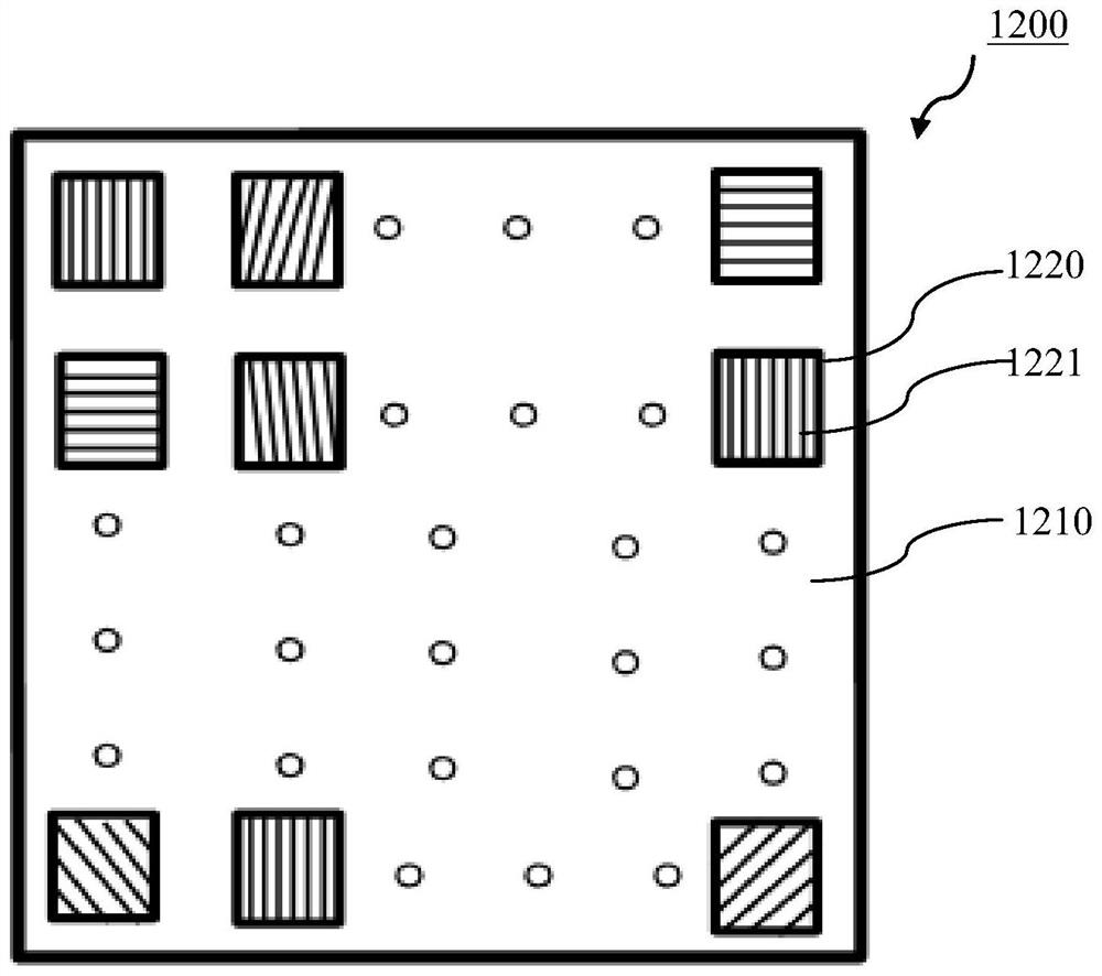
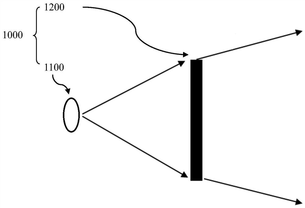
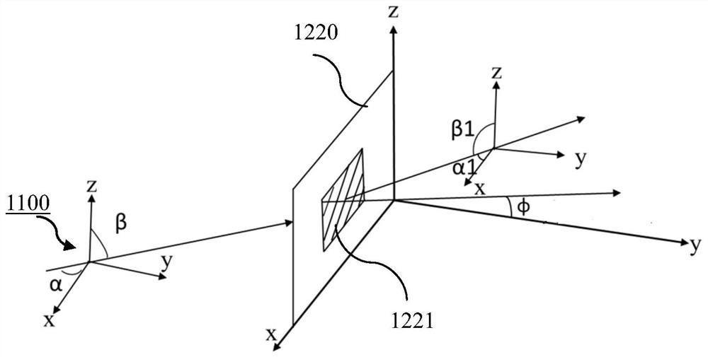
The invention provides a laser radar transmitting terminal and a method for preparing the laser radar transmitting terminal. The laser radar transmitting terminal comprises a light source module and a diffraction module, wherein the light source module comprises at least one laser light source; the diffraction module is arranged on an optical path of the light emitted by the light source module and is used for performing optical diffraction processing on the light emitted by the light source module; and the diffraction module comprises a plurality of single gratings to deflect the light emitted by the light source module so that the diffracted light achieves an expected diffraction angle. The laser radar transmitting terminal is advantaged in that emitted light of the laser radar transmitting terminal can realize a farther detection distance.

Description

technical field [0001] The present application relates to the technical field of optical equipment, and more specifically, to a laser radar transmitter. Background technique [0002] LiDAR plays an important role in unmanned driving. Traditional LiDAR emitters can be divided into the following categories: emitters based on orthogonal cylindrical mirrors, emitters based on floodlighting diffusers, and traditional diffraction-based emitters. The (non-grating) emitting end of a component. Among them, the emitting end based on the orthogonal cylindrical mirror and the emitting end based on the diffusion plate both adopt flood lighting. Since the actual photosensitive area of ​​the chip at the receiving end of the lidar only accounts for about 18% of the chip area, the emitting end When flood lighting is used, most of the emitted light cannot be received by the photosensitive area; and the emitting end based on the diffraction element, because the light emitted by it is a dot ma...

Claims


Application Information

Patent Timeline
IPC IPC(8): G01S17/02G01S17/08G01S7/481
CPCG01S17/02G01S7/4814
Inventor 吴尚亮陈俊逸谢前森
Owner NINGBO SUNNY AUTOMOTIVE OPTECH
Why Eureka
Try Eureka