
Tree thermal insulation layer winding equipment

A technology of insulation layer and trees, which is applied in the field of gardens, can solve the problems of freezing to death, lack of thermal insulation effect of trees, and failure of thermal insulation effect, etc., and achieve the effect of smooth rotation and energy saving

Inactive Publication Date: 2022-01-07
杨振清
View PDF0 Cites 0 Cited by
  • Summary
  • Abstract
  • Description
  • Claims
  • Application Information

AI Technical Summary

Problems solved by technology

[0002] A large number of trees will be planted on both sides of the road to improve the surrounding environment, but in the cold winter, in order to prevent the trees from being frostbitten and freeze to death, straw ropes will be used to wrap the trees around the trees to keep the trees warm, but at present The trees are all wound by hand, so during the winding process, the grass rope cannot be tightly wound on the trees, so the heat preservation effect on the trees cannot be achieved, and the trees will still be frostbitten or frozen to death, and the trees will fall off The bark of the tree adheres to the tree, and there is a gap between the tree and the bark. Similarly, the straw rope is used to wrap the bark that is about to fall off on the tree, so that there is a gap between the tree and the bark that is about to fall off, so it is still not enough. To achieve the required thermal insulation effect, so the tree thermal insulation layer winding equipment is proposed here

Method used


Image

  • Tree thermal insulation layer winding equipment
  • Tree thermal insulation layer winding equipment
  • Tree thermal insulation layer winding equipment

Examples


Embodiment Construction

[0034] The following will clearly and completely describe the technical solutions in the embodiments of the present invention with reference to the accompanying drawings in the embodiments of the present invention. Obviously, the described embodiments are only some, not all, embodiments of the present invention. Based on the embodiments of the present invention, all other embodiments obtained by persons of ordinary skill in the art without making creative efforts belong to the protection scope of the present invention.

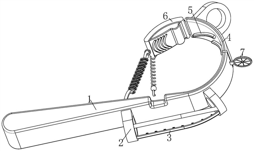
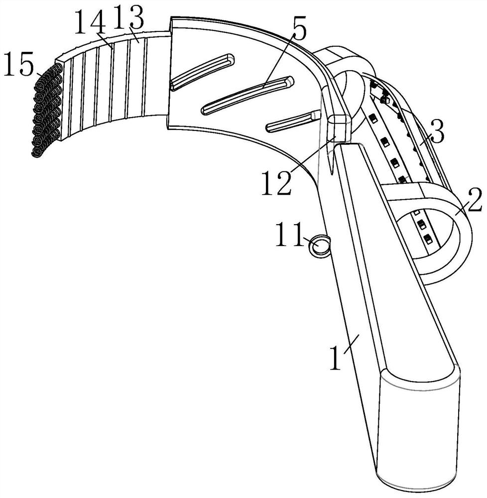
[0035] see Figure 1-6 , the present invention provides a technical solution: a kind of tree insulation layer winding equipment, including a grip rod 1, one end of the grip rod 1 is arranged in an arc shape, and one end of the grip rod 1 is arranged in an arc shape. 4 An auxiliary arc-shaped metal 6 is provided at the end away from the handle 1;

[0036] One side of the grip bar 1 is fixedly installed with a guide rope cover 2, and the protruding side of the ...


PUM


Abstract

The invention relates to the technical field of gardens, and discloses tree thermal insulation layer winding equipment which comprises a holding rod, wherein one end of the holding rod is arc-shaped, arc-shaped metal is clamped at the arc-shaped end of the holding rod, auxiliary arc-shaped metal is arranged at the end, away from the holding rod, of the arc-shaped metal, a rope guide sleeve I is fixedly installed on one side of the holding rod, a rope guide sleeve II which is obliquely arranged is fixedly mounted on one bulging side of the arc-shaped metal, and a metal strip is fixedly connected between the rope guide sleeve I on the holding rod and the rope guide sleeve II. According to the tree thermal insulation layer winding equipment, a special-shaped spring is buckled on the metal strip, the metal strip is bent, metal spikes on the metal strip puncture a straw rope, the metal spikes are arranged in two halves and move towards the two sides in the puncturing process to buckle the straw rope, the straw rope is clamped in semicircular openings, and the straw rope is prevented from sliding; and the section of the special-shaped spring is arranged in a hexagonal shape, the special-shaped spring is hooked and then is in contact with the tree, so that the equipment can be well prevented from reversing and loosening, and the purpose that an operator has a rest is achieved.

Description

technical field [0001] The invention relates to the technical field of gardens, in particular to a tree insulation layer winding device. Background technique [0002] A large number of trees will be planted on both sides of the road to improve the surrounding environment, but in the cold winter, in order to prevent the trees from being frostbitten and freeze to death, straw ropes will be used to wrap the trees around the trees to keep the trees warm, but at present The trees are all wound by hand, so during the winding process, the grass rope cannot be tightly wound on the trees, so the heat preservation effect on the trees cannot be achieved, and the trees will still be frostbitten or frozen to death, and the trees will fall off The bark of the tree adheres to the tree, and there is a gap between the tree and the bark. Similarly, the straw rope is used to wrap the bark that is about to fall off on the tree, so that there is a gap between the tree and the bark that is about ...

Claims


Application Information

Patent Timeline
IPC IPC(8): A01G13/02
CPCA01G13/0237
Inventor 杨振清
Owner 杨振清
Learn More