Gear transmission structure of tracked robot

A technology of gear transmission and robotics, which is applied to motor vehicles, crawler vehicles, transportation and packaging, etc., can solve the problems of inconvenient fixed diameter of the front gear, and achieve the effects of improving field survivability and continuous operation ability, improving efficiency, and simple structure

Pending Publication Date: 2022-01-07
QINGDAO BRANCH CO., LTD. OF MECHANICAL SCIENCE RESEARCH INSTITUTE
View PDF0 Cites 0 Cited by
  • Summary
  • Abstract
  • Description
  • Claims
  • Application Information

AI Technical Summary

Problems solved by technology

[0003] The present invention solves the problem that the diameter of the front gear of the existing crawler robot is fixed and inconvenient. It can only overcome obstacles whose height is smaller than the radius of the front gear. For some obstacles whose height is greater than the radius of the front gear, the diameter can be bypassed or passed through by building a slope. problem, and then propose a crawler robot gear transmission structure

Method used


Image

  • Gear transmission structure of tracked robot
  • Gear transmission structure of tracked robot
  • Gear transmission structure of tracked robot

Examples


specific Embodiment approach 1

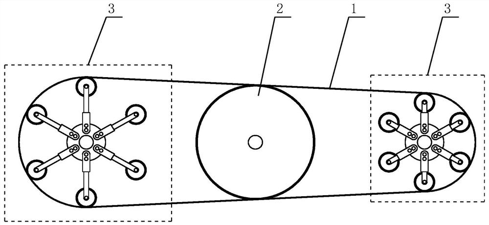
[0018] Specific implementation mode one: combine Figure 1 to Figure 4 Describe this embodiment, a crawler robot gear transmission structure described in this embodiment, which includes a crawler belt 1; this embodiment also includes an intermediate transition gear 2 and two reducing gear mechanisms 3; the intermediate transition gear 2 is arranged on two Between the reducing gear mechanisms 3 , the crawler belt 1 is sleeved on the intermediate transition gear 2 and the two reducing gear mechanisms 3 .

specific Embodiment approach 2

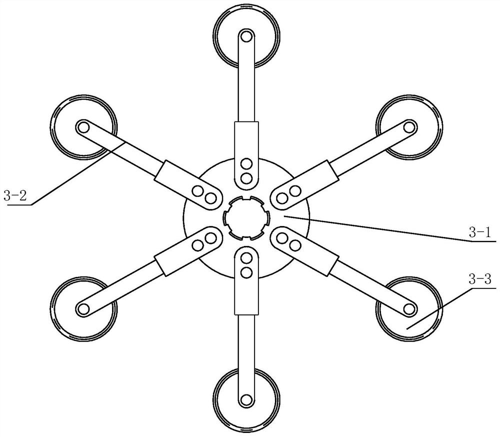
[0019] Specific implementation mode two: combination Figure 1 to Figure 4 To illustrate this embodiment, the reducing gear mechanism 3 of a crawler robot gear transmission structure described in this embodiment includes a wheel disc 3-1, six electrohydraulic cylinder assemblies 3-2 and six fixed gear assemblies 3-3; Six electro-hydraulic cylinder assemblies 3-2 are evenly arranged on the edge of the wheel disc 3-1 along the circumferential direction, and one end of each electro-hydraulic cylinder 3-2 is fixedly connected with the wheel disc 3-1, and each electro-hydraulic cylinder 3- The other end of 2 is fixedly connected with a fixed gear assembly 3-3. Other components and connections are the same as those in the first embodiment.

specific Embodiment approach 3

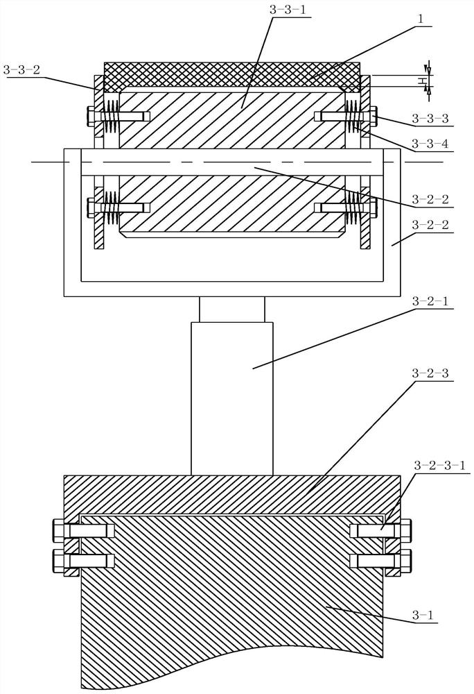
[0020] Specific implementation mode three: combination Figure 1 to Figure 4 To illustrate this embodiment, each electric hydraulic cylinder assembly 3-2 of a crawler robot gear transmission structure described in this embodiment includes an electric hydraulic cylinder 3-2-1, an outer frame 3-2-2 and an inner frame 3-2-3; the cylinder body of the electric hydraulic cylinder 3-2-1 is fixedly connected with the inner frame 3-2-3, and the piston rod of the electric hydraulic cylinder 3-2-1 is fixed with the outer frame 3-2-2 connection, the inner insert frame 3-2-3 is fixedly connected with the wheel disc 3-1, and the outer insert frame 3-2-2 is fixedly connected with the fixed gear assembly 3-3. Other components and connections are the same as those in the second embodiment.


PUM


Abstract

The invention discloses a gear transmission structure of a tracked robot, and relates to a gear transmission structure, in particular to the gear transmission structure of the tracked robot. The problems that the diameter of the front gear of an existing tracked robot is inconvenient to fix, the existing tracked robot can only climb over and overcome obstacles with the height smaller than the radius of the front gear, and some obstacles with the height larger than the radius of the front gear bypass or pass through in a slope building mode are solved. The gear transmission structure comprises a middle transition gear and two variable-diameter gear mechanisms; the middle transition gear is arranged between the two variable-diameter gear mechanisms, and the crawler belt is arranged on the middle transition gear and the two variable-diameter gear mechanisms in a sleeving mode. The invention belongs to the field of gear structure design.

Description

technical field [0001] The invention relates to a gear transmission structure, in particular to a crawler robot gear transmission structure, and belongs to the field of gear structure design. Background technique [0002] Tracks are driven by flexible links surrounding the drive pulley, road wheels, idlers and track rollers. The track is composed of track shoes and track pins. The track pins connect the track shoes to form a track link. There are holes at both ends of the track shoe, which mesh with the driving wheel, and there are inducing teeth in the middle, which are used to straighten the track and prevent the track from falling off when the tank turns or rolls. Improve the firmness of the track shoe and the adhesion between the track and the ground. A robot that uses a crawler as a chassis to walk is called a crawler robot. A crawler robot can adapt to a variety of complex terrains, so it is widely used in field transportation, reconnaissance and other activities. ...

Claims


Application Information

Patent Timeline
Patent Type & Authority Applications(China)
IPC IPC(8): B62D55/12
CPCB62D55/12
Inventor 张康战丽李云鹏
Owner QINGDAO BRANCH CO., LTD. OF MECHANICAL SCIENCE RESEARCH INSTITUTE
Why Eureka
Try Eureka