Ball valve with pressure relief function

A ball valve and function technology, applied in the field of ball valves with pressure relief function, can solve the problems of ball valve damage, inconvenient installation and disassembly, and high maintenance costs

Active Publication Date: 2022-01-07
JINGGONG VALVE
View PDF9 Cites 2 Cited by
  • Summary
  • Abstract
  • Description
  • Claims
  • Application Information

AI Technical Summary

Problems solved by technology

[0005] Aiming at the deficiencies of the prior art, the present invention provides a ball valve with pressure relief function, which solves the problem of inconvenient installation and disassembly of the traditional ball valve during pressure relief, which leads to inconvenience and high maintenance cost in the later stage, and also easily causes damage to the ball valve. question

Method used


Image

  • Ball valve with pressure relief function
  • Ball valve with pressure relief function
  • Ball valve with pressure relief function

Examples


Embodiment 1

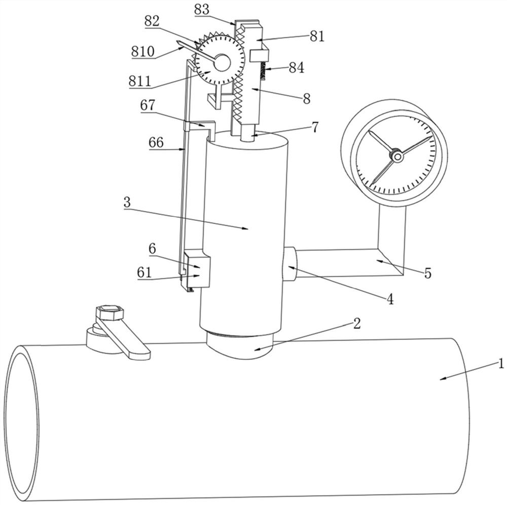
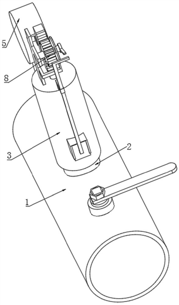
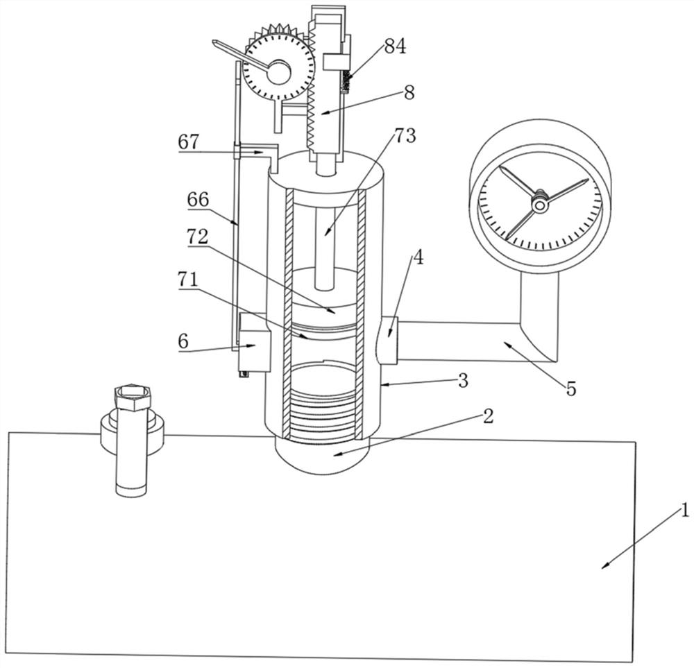
[0028]A ball valve with a pressure relief function, comprising a ball valve body 1, the outer surface of the ball valve body 1 is fixedly connected with a first threaded joint 2, the outer surface of the first threaded joint 2 is threaded with a piston barrel 3, and the lower part of the outer surface of the piston barrel 3 is fixedly connected There is a second threaded joint 4, the inner cavity of the second threaded joint 4 is threadedly connected with a pressure gauge 5, the outer surface of the piston barrel 3 is fixedly connected with a pressure relief device 6, the inner cavity of the piston barrel 3 is equipped with a piston device 7, and the upper surface of the piston device 7 An adjustment device 8 is fixedly connected. The pressure discharge device 6 is composed of a rectangular hole 61, an L-shaped groove 62, an L-shaped sealing plate 63, a first telescopic rod 64, a return spring 65, a mounting rod 66 and a support rod 67, and the outer surface of the piston barre...


PUM


Abstract

The invention discloses a ball valve with a pressure relief function. The ball valve comprises a ball valve body, the outer surface of the ball valve body is fixedly connected with a first threaded connector, the outer surface of the first threaded connector is in threaded connection with a piston barrel, and the lower portion of the outer surface of the piston barrel is fixedly connected with a second threaded connector. An inner cavity of the second threaded connector is in threaded connection with a pressure gauge, a pressure discharging device is fixedly connected to the outer surface of the piston barrel, a piston device is installed in an inner cavity of the piston barrel, and an adjusting device is fixedly connected to the upper end face of the piston device. The invention relates to the technical field of ball valves with the pressure relief function. According to the ball valve with the pressure relief function, the problems that due to the fact that a traditional ball valve is inconvenient to install and detach during pressure relief, later maintenance is inconvenient, the maintenance cost is high, and meanwhile the ball valve is likely to be damaged are solved.

Description

technical field [0001] The invention relates to the technical field of ball valves with pressure relief function, in particular to a ball valve with pressure relief function. Background technique [0002] Ball valve, the opening and closing part (ball) is driven by the valve stem and rotates around the axis of the ball valve. It can also be used for the regulation and control of fluids, among which the hard-sealed V-shaped ball valve has a strong shear force between its V-shaped ball core and the metal valve seat of surfacing welding carbide, and is especially suitable for fibers and tiny solid particles. etc. medium. The multi-way ball valve can not only flexibly control the confluence, diversion, and flow direction switching of the medium on the pipeline, but also close any channel and connect the other two channels. This type of valve should generally be installed horizontally in the pipeline. According to the driving mode, the ball valve is divided into: pneumatic bal...

Claims


Application Information

Patent Timeline
Patent Type & Authority Applications(China)
IPC IPC(8): F16K5/06F16K5/08F16K27/06F16K31/54F16K37/00F16K39/02
CPCF16K5/06F16K5/08F16K39/028F16K37/0016F16K27/067F16K31/54
Inventor 谢建国杨杰王学鹏徐洁娄近春邵忠武杨连成
Owner JINGGONG VALVE
Why Eureka
Try Eureka