
Accurate control rocket with control cabin section and gliding extended range cabin section

A technology of precise control and control cabin, applied in the direction of projectiles, self-propelled bombs, offensive equipment, etc., can solve the problem of gliding range extension and precise control of landing point that cannot be realized by a single control method, increase structural quality and structural complexity, and rocket structure and complex control mechanism to achieve the effect of improving gliding performance, low cost, and increasing flight distance

Pending Publication Date: 2022-01-07
BEIHANG UNIV +1
View PDF0 Cites 0 Cited by
  • Summary
  • Abstract
  • Description
  • Claims
  • Application Information

AI Technical Summary

Problems solved by technology

[0005] Traditional gliding range-extending rockets mainly control the gliding range-extending by using steering gears with different aerodynamic layouts. The structure and control mechanism of the rocket are relatively complicated, and the general gliding range-extending and the precise control of the landing point cannot be realized by a single control method, which greatly increases the structure. Mass and Structural Complexity
On the other hand, due to the change of the aerodynamic layout of the traditional gliding extended range rocket, it is not suitable for the information transformation of the traditional stock uncontrolled rocket

Method used


Image

  • Accurate control rocket with control cabin section and gliding extended range cabin section
  • Accurate control rocket with control cabin section and gliding extended range cabin section
  • Accurate control rocket with control cabin section and gliding extended range cabin section

Examples


Embodiment Construction

[0056] The present invention will be further described below in conjunction with the drawings.

[0057] Implementation example:

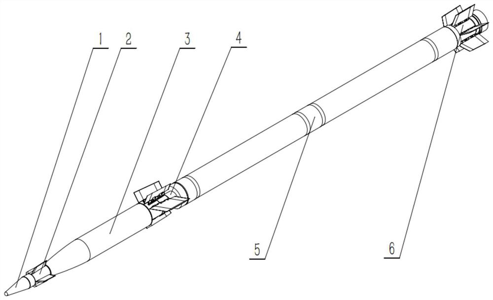
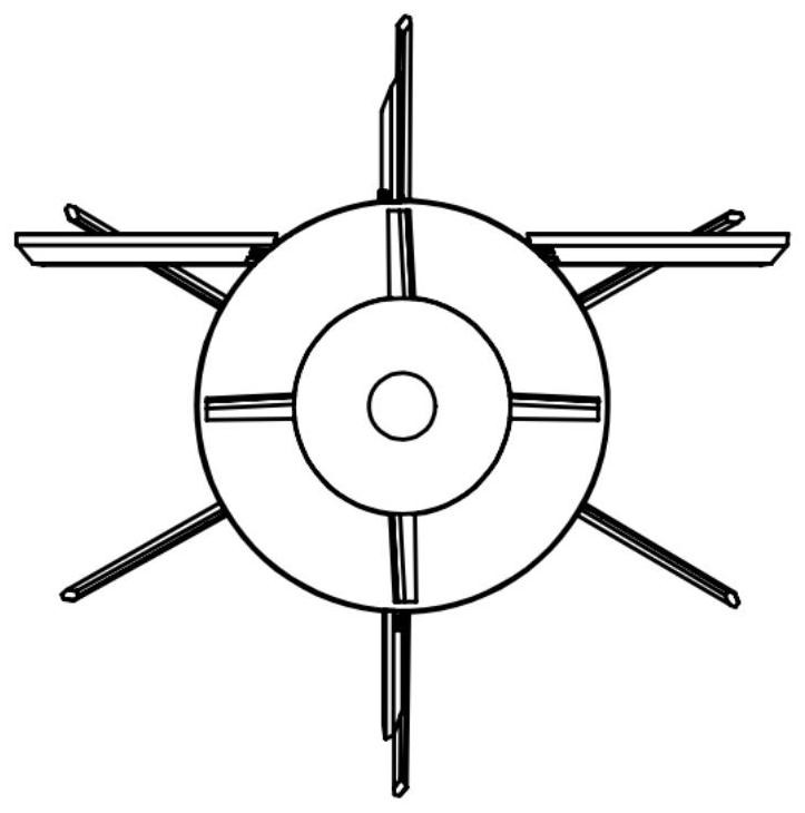
[0058] Such as figure 1 -Shown in 4, a kind of precise control rocket with control cabin section and gliding range extension cabin section of the present invention comprises: load control assembly (1), control cabin section (2), load cabin (3), range extension cabin section (4), engine (5), empennage assembly (6), wherein the control module (2) and the extended range module (4) realize information interconnection through the connection (30) pre-embedded in the load compartment (3) ( For the informatization transformation of the rocket, the information interconnection can be realized through the wireless transmission module); wherein the load control component (1) is located at the head of the rocket, and the control cabin (2) is connected with the load control component (1) behind it, and the load cabin (3 ) is connected with the control cabin (2)...


PUM


Abstract

The invention discloses a rocket overall scheme for performing gliding extended range and accurate control by using an extended range cabin section and a control cabin section, and aims to realize extended range and accurate control over a landing point. The rocket overall scheme is characterized in that the control cabin section is additionally arranged at the head of a rocket, a correction rudder on the control cabin section generates aerodynamic force perpendicular to the direction of a rudder surface in the flight process, the direction of the aerodynamic force is controlled by rolling a canard rudder base on the control cabin section, and accurate control over the landing point is achieved; and the extended range cabin section is additionally arranged in the middle, a pair of expandable lift wings on the extended range cabin section generate aerodynamic force perpendicular to the wing surface direction in the flight process, the aerodynamic force direction is controlled by rolling and rotating wing seats of the extended range cabin section, and gliding extended range is achieved. Rotation reduction rudders and rotation reduction wings mainly provide rotation reduction torque for realizing rotation reduction of the canard rudder base and the extended range cabin wing base, and serves as control torque of a load balance control motor. According to the rocket overall scheme, accurate control over the landing point of the rocket can be achieved on the basis that the flight distance of the rocket is effectively increased.

Description

technical field [0001] The invention relates to an overall plan of a rocket which utilizes a range-extending cabin section to realize gliding range-extending and uses a control cabin section to realize precise control of flight, and realizes the precise control of the rocket range extension and the rocket landing point. Background technique [0002] Complex application scenarios put forward higher requirements on the cost-effectiveness ratio and precise control performance of rockets, which promotes the development of modern rocket systems in the direction of precise control and long-distance targets. At the same time, the rapid innovation of technology, especially the rapid development of electronic information technology, has provided strong technical support for the development of rockets from uncontrolled to autonomous guidance. [0003] Traditional rockets are generally an application carrier that requires an inaccurate range of action. The development of precise contro...

Claims


Application Information

Patent Timeline
Patent Type & Authority Applications(China)
IPC IPC(8): F42B15/00F42B15/01F42B10/38F42B10/06F42B10/64
CPCF42B15/00F42B15/01F42B10/38F42B10/06F42B10/64
Inventor 王华程浩翟小丽苏建利冯修源马超越魏炜黄海鹏
Owner BEIHANG UNIV
Learn More