Stator leading-out wire structure of air internal-cooling generator

A generator stator, air cooling technology, applied in the direction of electromechanical devices, electrical components, electric components, etc., can solve the problems of large current, hidden safety hazards, limited basic space of generators, etc.

Active Publication Date: 2022-01-07
华能伊敏煤电有限责任公司汇流河热电分公司 +1
View PDF6 Cites 0 Cited by
  • Summary
  • Abstract
  • Description
  • Claims
  • Application Information

AI Technical Summary

Problems solved by technology

[0002] The lead-out wires of large-scale turbogenerators are mainly used to lead out electric energy. They are the key components of generators and have the characteristics of high voltage and large current. It is relatively large, and there is a strong alternating magnetic field around the lead wires, which will cause a concentration force between the lead wires and cause a safety hazard, especially when the generator is running under abnormal conditions, the heat and concentration force of the lead wires will be greater, such as If it cannot dissipate heat efficiently and fix it effectively, it may cause serious accidents
[0003] Therefore, the design of the lead-out line needs to consider both ventilation and cooling and mechanical fixation. In the past, the lead-out line was located in the cold wind area of ​​the generator and could be cooled naturally by the cold air from the cooler. For reverse ventilation, the lead wires are placed in the hot air area of ​​the generator, and the space inside the generator foundation is limited, the ventilation conditions in the lead wire area are poor, and it is difficult to form heat exchange with the outside world. If the heat cannot be reliably dissipated, the lead wires may burn out and cause serious accidents

Method used


Image

  • Stator leading-out wire structure of air internal-cooling generator
  • Stator leading-out wire structure of air internal-cooling generator
  • Stator leading-out wire structure of air internal-cooling generator

Examples


Embodiment Construction

[0025] The present invention will be further described below in conjunction with the accompanying drawings and specific embodiments.

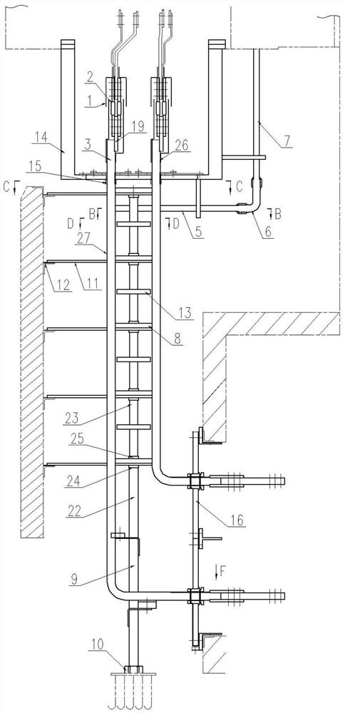
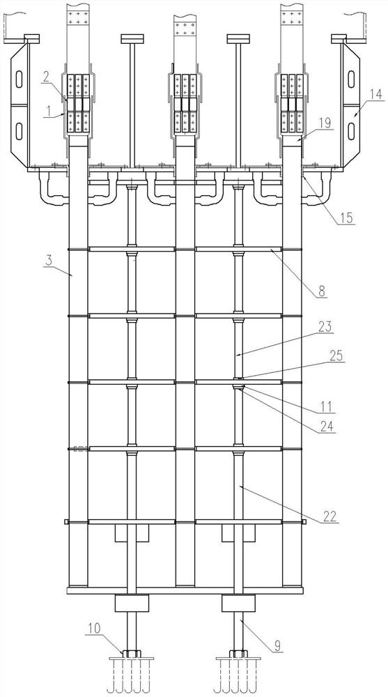
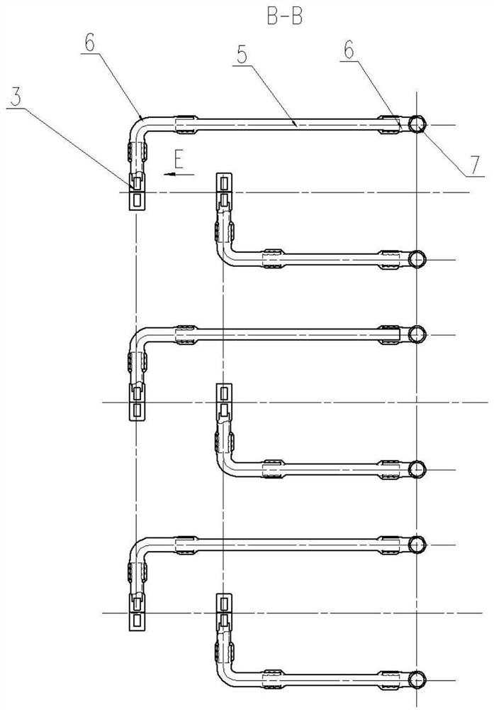
[0026] Such as figure 1 and Figure 9 As shown, the cooling air enters from the air inlet of the insulation box 1 at the lead end, flows through the flexible connection 2, and enters the copper bar 3 in parallel. The insulation box 1 is divided into upper and lower halves. Partially open the mask and leave a certain gap, which can ensure smooth air intake and prevent foreign matter such as dust from entering the internal air duct. The cross-section of the copper bar 3 is as follows: Figure 8 , which is in the shape of "day", and the outer wrapping insulation is 18. Such as Figure 5 As shown, a blocking plate 4 is placed in front of the horizontal air outlet pipe 5 to block one air path of the copper bar, and a hole is opened in the middle partition between the two air paths in front of the blocking plate 4, so that the two air inlets can b...


PUM


Abstract

The invention provides a stator leading-out wire structure of an air internal-cooling generator, which adopts a hollow conductive copper bar with a section shaped like a Chinese character 'ri', forms a U-shaped loop ventilating duct inside, and can generate internal circulation through pressure difference by means of special air duct design and the characteristic that fan pressure difference exists between aleading-out wire box and a fan front wind area of the generator. Cold air is led into the copper bar from an insulation box at the head end of the lead, flows through the whole copper bar and flows out of a front wind area of a generator at the head end of the lead, heat consumption generated by the copper bar is directly taken away by cooling air flowing through a conductor, air in the whole main lead is directly cooled, the heat dissipation effect can be effectively improved, and the purpose of controlling temperature rise is achieved. And the temperature rise meets the national standard and standard requirements.

Description

technical field [0001] The invention relates to the technical field of turbogenerators, in particular to a stator lead-out wire structure of an air-internal cooling generator. Background technique [0002] The lead-out wires of large-scale turbogenerators are mainly used to lead out electric energy. They are the key components of generators and have the characteristics of high voltage and large current. It is relatively large, and there is a strong alternating magnetic field around the lead wires, which will cause a concentration force between the lead wires and cause a safety hazard, especially when the generator is running under abnormal conditions, the heat and concentration force of the lead wires will be greater, such as Failure to efficiently dissipate heat and fix it effectively may cause serious accidents. [0003] Therefore, the design of the lead-out line needs to consider both ventilation and cooling and mechanical fixation. In the past, the lead-out line was loc...

Claims


Application Information

Patent Timeline
Patent Type & Authority Applications(China)
IPC IPC(8): H02K3/50H02K5/22H02K5/20H02K9/04H02K9/08
CPCH02K3/50H02K5/225H02K5/207H02K9/04H02K9/08Y02E10/72
Inventor 陶泽宇黄浩孙昌海朱志佳吴春闫雪超刘建平张万兵李国金王帆徐龙坤郝全华张亚楠寇成宝刘金亮
Owner 华能伊敏煤电有限责任公司汇流河热电分公司
Why Eureka
Try Eureka