Rectifying circuit suitable for low-voltage alternating current input and high-voltage direct current output

A technology of AC input and high-voltage DC, which is applied in the direction of converting AC power input into DC power output, DC power input into DC power output, and output power conversion devices, etc., which can solve the problem of high-frequency ripple current processing. Problems such as large current rectification conduction loss and conversion loss, low conversion efficiency with high DC boost ratio, etc., to achieve the effects of expanding enterprise production benefits, low loss rectification and boosting, improving power density and conversion efficiency

Pending Publication Date: 2022-01-07
深圳市力源海纳能源有限公司
View PDF0 Cites 0 Cited by
  • Summary
  • Abstract
  • Description
  • Claims
  • Application Information

AI Technical Summary

Problems solved by technology

[0002] At present, low-voltage AC needs to be rectified, boosted and converted into high-voltage DC, and then converted to off-grid or grid-connected to realize power generation. Due to the relatively large conduction loss and conversion loss of high-current rectification, and the high-frequency ripple current The processing difficulty is also relatively high, resulting in low conversion efficiency of DC high boost ratio

Method used


Image

  • Rectifying circuit suitable for low-voltage alternating current input and high-voltage direct current output
  • Rectifying circuit suitable for low-voltage alternating current input and high-voltage direct current output
  • Rectifying circuit suitable for low-voltage alternating current input and high-voltage direct current output

Examples


Embodiment Construction

[0017] In order to make the object, technical solution and advantages of the present invention clearer, the present invention will be further described in detail below in conjunction with the accompanying drawings and implementation examples. It should be understood that the specific embodiments described here are only used to explain the present invention, not to limit the present invention.

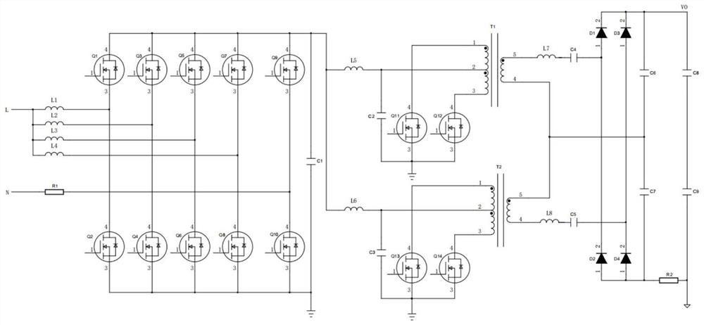
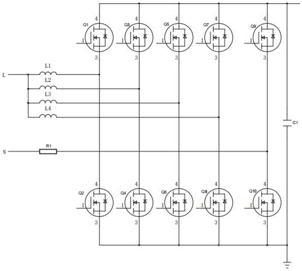
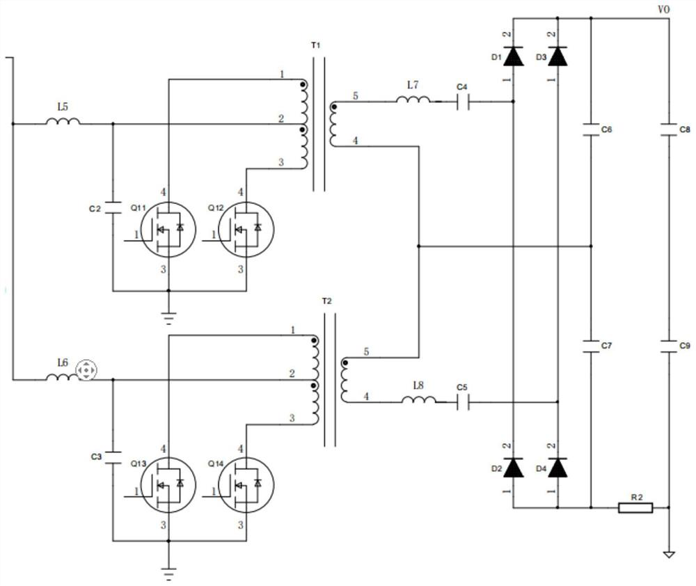
[0018] see Figure 1-Figure 4 , the present invention provides a rectifier circuit 10 suitable for low-voltage AC input and high-voltage DC output, including an interleaved totem pole PFC topology circuit 11, an interleaved push-pull resonant soft switching topology circuit 12 and a Π-type filter circuit 13, an interleaved totem pole The PFC topology circuit 11 is electrically connected to the Π-type filter circuit 13, and the Π-type filter circuit 13 is electrically connected to the interleaved push-pull resonant soft-switching topology circuit 12.

[0019] Further, the interleaved to...


PUM


Abstract

The invention belongs to the technical field of rectifying circuits, and relates to a rectifying circuit suitable for low-voltage alternating current input and high-voltage direct current output. The rectifying circuit comprises an interlaced totem pole PFC topological circuit, an interlaced push-pull resonant soft switch topological circuit and an n-shaped filter circuit; the interlaced totem pole PFC topological circuit is electrically connected with the n-shaped filter circuit; and the n-shaped filter circuit is electrically connected with the interlaced push-pull resonant soft switch topological circuit. According to the rectifying circuit suitable for low-voltage alternating current input and high-voltage direct current output, by means of the interlaced totem pole PFC topological circuit and the interlaced push-pull resonant soft switch topological circuit, low-loss rectifying and boosting of large current are achieved, and meanwhile distributed diversion is achieved, input and output high-frequency ripple current is reduced, filtering parameters are reduced, power density and conversion efficiency are improved, cost expenditure related to the circuit is reduced, and production benefits of enterprises can be increased.

Description

【Technical field】 [0001] The invention relates to the technical field of rectification circuits, in particular to a rectification circuit suitable for low-voltage AC input and high-voltage DC output. 【Background technique】 [0002] At present, low-voltage AC needs to be rectified, boosted and converted into high-voltage DC, and then converted to off-grid or grid-connected to realize power generation. Due to the relatively large conduction loss and conversion loss of high-current rectification, and the high-frequency ripple current The processing difficulty is also relatively high, resulting in low conversion efficiency of DC high boost ratio. [0003] Therefore, there are deficiencies in the prior art and need to be improved. 【Content of invention】 [0004] To overcome the above technical problems, the present invention provides a rectifier circuit suitable for low-voltage AC input and high-voltage DC output. [0005] The solution to the technical problem of the present ...

Claims


Application Information

Patent Timeline
Patent Type & Authority Applications(China)
IPC IPC(8): H02M7/217H02M3/335H02M3/337H02M1/42H02M1/14H02M1/12
CPCH02M7/217H02M3/33569H02M3/337H02M1/4225H02M1/126H02M1/14Y02B70/10
Inventor 方耿黄瑞炉
Owner 深圳市力源海纳能源有限公司
Why Eureka
Try Eureka