Weighing coal feeder based on high efficiency
A coal feeder and weighing technology, which is applied in the direction of weighing equipment, weighing, conveyors, etc. of continuous material flow, can solve the problems of operation influence and inaccurate coal loading, so as to increase the coal loading rate and reduce cleaning The frequency of the conveyor belt and the effect of improving work efficiency
- Summary
- Abstract
- Description
- Claims
- Application Information
AI Technical Summary
Problems solved by technology
Method used
Image
Examples
Embodiment 1
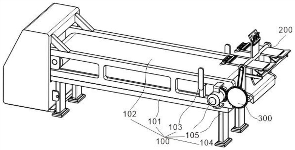
[0027] refer to figure 1 and figure 2 , is the first embodiment of the present invention, which provides a high-efficiency weighing coal feeder based on a high-efficiency weighing coal feeder including a coal feeder assembly 100 and a coal drop assembly 200, and the coal feeder assembly 100 is used for coal feeding operation, and the arrangement of coal dropping assembly 200 improves the efficiency and accuracy of coal lowering.
[0028] Specifically, the coal feeder assembly 100 includes a frame 101, a conveyor belt 102, a weighing device 103, a support column 104, and a drive motor 105, the conveyor belt 102 is located inside the frame 101, and the weighing device 103 is arranged below the conveyor belt 102 , the supporting columns 104 are fixed at the four corners of the bottom of the frame 101 , and the conveyor belt 102 is driven by a driving motor 105 .
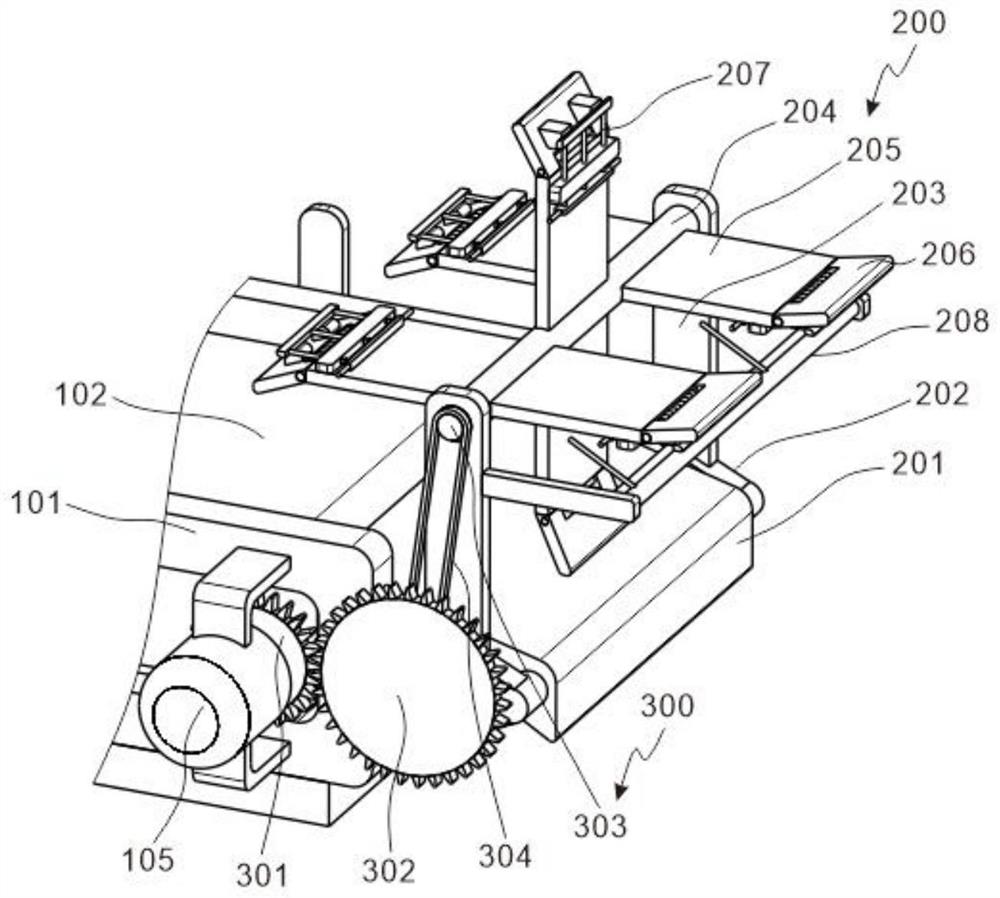
[0029] refer to figure 2 , the driving motor 105 is fixed on one side of the frame 101 through an L-shaped block...
Embodiment 2
[0034] refer to figure 2 , is the second embodiment of the present invention, which is based on the previous embodiment.
[0035] Specifically, it also includes a transmission assembly 300, which is arranged on one side of the coal drop assembly 200, including a driving gear 301, a driven gear 302, a transmission shaft 303 and a transmission belt 304, and the driving gear 301 is fixed on the output end of the drive motor 105, from which Driven gear 302 and supporting plate 202 rotate and cooperate, driven gear 302 meshes with driving gear 301 , transmission shaft 303 is fixed with fixed rod 204 , between driven gear 302 and transmission shaft 303 through transmission belt 304 and cooperate.
[0036] refer to figure 2 , the diameter of the driving gear 301 is less than the diameter of the driven gear 302, so that the rotating speed of the driven gear 302 is less than the rotating speed of the driving gear 301, so as to avoid the excessive speed of the fixed rod 204 and affect ...
Embodiment 3
[0039] refer to image 3 and Figure 4 , is the third embodiment of the present invention, which is based on the first two embodiments.
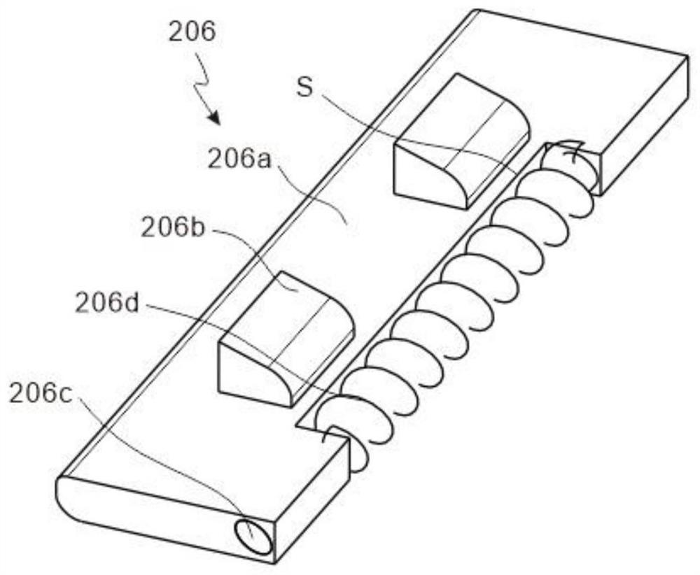
[0040] Specifically, the coal cutting piece 206 includes a coal cutting plate 206a, a fixed block 206b and a fixed shaft 206c, the coal cutting plate 206a and the fixed plate 205 are hinged through the fixed shaft 206c, and the fixed block 206b is fixed on one side of the coal cutting plate 206a.
[0041] refer to image 3 , the coal cutting plate 206a is hinged with the fixed plate 205, and the side of the coal cutting plate 206a away from the fixed plate 205 is chamfered, and is tangent to the scraper 201; there are two fixed blocks 206b, which are symmetrically distributed on the coal cutting plate 206a It is convenient to limit the position of the coal cutting plate 206a and improve its coal cutting effect.
[0042] The coal cutting piece 206 also includes a through hole S opened on the coal cutting plate 206a, and a return spring 206...
PUM
 Abstract
Description
Claims
Application Information
 - R&D
- Intellectual Property
- Life Sciences
- Materials
- Tech Scout
- Unparalleled Data Quality
- Higher Quality Content
- 60% Fewer Hallucinations
Browse by: Latest US Patents, China's latest patents, Technical Efficacy Thesaurus, Application Domain, Technology Topic, Popular Technical Reports.
© 2025 PatSnap. All rights reserved.Legal|Privacy policy|Modern Slavery Act Transparency Statement|Sitemap|About US| Contact US: help@patsnap.com


