Coating production filling device capable of facilitating metering

A filling device and coating technology, which is applied in the safety device of the filling device, packaging, liquid bottling, etc., can solve the problems of inaccurate placement, injection, and increased filling costs

Active Publication Date: 2022-01-11
澳昌(武汉)生态科技有限公司
View PDF8 Cites 0 Cited by
  • Summary
  • Abstract
  • Description
  • Claims
  • Application Information

AI Technical Summary

Problems solved by technology

[0003] Existing paint production and filling devices can often only fill the packaging tanks of the same specification, and cannot measure the filling of packaging tanks of different sizes, making it difficult to accurately inject a specified amount of paint into different packaging tanks. At the same time, due to the size limitation of the packaging tank limit structure, it is impossible to accurately place a packaging tank smaller than the original size on the existing paint production and filling device, so that it is impossible to realize one machine with multiple functions, which in turn increases the cost of filling.

Method used


Image

  • Coating production filling device capable of facilitating metering
  • Coating production filling device capable of facilitating metering
  • Coating production filling device capable of facilitating metering

Examples


Embodiment 1

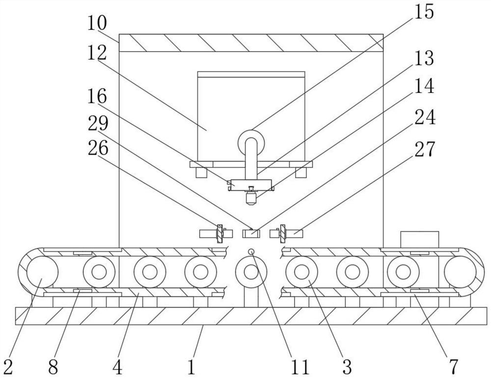
[0025] As shown in the drawings, the embodiment of the present invention provides a convenient metering paint production and filling device, including a base 1, a driving roller 2 is installed on the top side of the base 1, and a speed reducer 5 is installed on the outer wall of the driving roller 2 , the outer side of the reducer 5 is equipped with a first motor 6, and the top side of the base 1 is evenly equipped with a plurality of supporting rollers 3 at a position far away from the driving roller 2, and the plurality of supporting rollers 3 and the outer surface of the driving roller 2 are sleeved There is a transmission belt 4, and the outer surface of the transmission belt 4 is evenly provided with a plurality of positioning grooves 7, and the inner bottom sides of the plurality of positioning grooves 7 are all embedded with a weighing module 8, and the outer side of the transmission belt 4 corresponds to the positioning groove 7 The positions on the sides are all embedd...

Embodiment 2

[0032] The structure of this embodiment is basically the same as that of Embodiment 1, the difference is that:

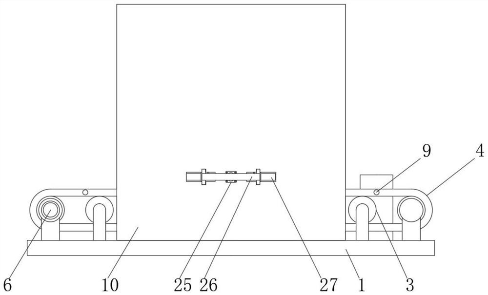
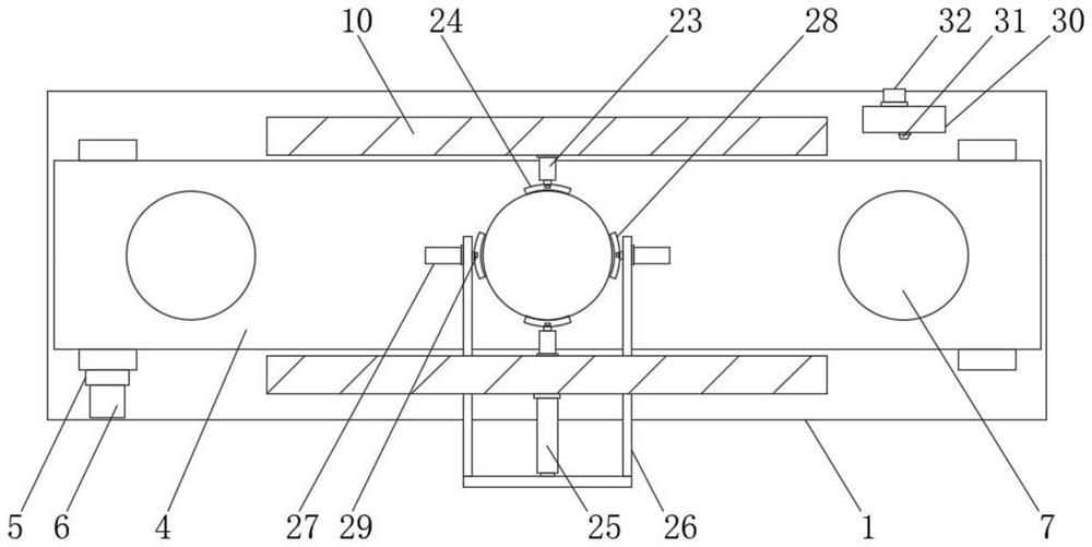
[0033] Specifically, the top of the base 1 is fixedly connected with a side frame 30 near the side of the support frame 10, the outer wall of the side frame 30 is equipped with an alarm horn 32, and the inner wall of the side frame 30 is equipped with a second infrared emitter 31, Facilitate when the packing can that injects paint is moved to side frame 30 one side, the infrared receiver 9 outside this positioning slot 7 is aimed at the second infrared emitter 31, then driving roller 2 stops, and alarm horn 32 sounds, so that The lifting staff will collect the packaging jars in time.

[0034] Specifically, the second infrared emitter 31 is on the same horizontal line as the first infrared emitter 11 , so that the second infrared emitter 31 can be aligned with the infrared receiver 9 like the first infrared emitter 11 .


PUM


Abstract

The invention provides a coating production filling device capable of facilitating metering, and relates to the technical field of coating production filling. The coating production filling device capable of facilitating metering comprises a base, a driving roller is arranged on the top side of the base, a speed reducer is arranged on the outer side wall of the driving roller, a first motor is arranged on the outer side of the speed reducer, and a plurality of supporting rollers are evenly arranged at the position, away from the driving roller, of the top side of the base. The outer surfaces of the supporting rollers and the outer surface of the driving roller are sleeved with a transmission belt, and a plurality of positioning grooves are evenly formed in the outer surface of the transmission belt. The positions of all first distance sensors are adjusted at the same time so that all the first distance sensors can detect the liquid level heights of the inner sides of different packaging cans, and the amount of the coating injected into each packaging can can be accurately mastered in cooperation with a weighing module.

Description

technical field [0001] The invention relates to the technical field of paint production and filling, in particular to a convenient metering paint production and filling device. Background technique [0002] Paint is coated on the surface of the object to be protected or decorated, and can form a continuous film firmly attached to the object to be coated, usually based on resin, or oil, or emulsion, with or without adding pigments, fillers, and adding corresponding Additives, viscous liquids prepared with organic solvents or water. [0003] Existing paint production and filling devices can often only fill the packaging tanks of the same specification, and cannot measure the filling of packaging tanks of different sizes, making it difficult to accurately inject a specified amount of paint into different packaging tanks. At the same time, due to the size limitation of the packaging can limit structure, it is impossible to accurately place the packaging cans smaller than the or...

Claims


Application Information

Patent Timeline
IPC IPC(8): B67C3/24B67C3/20B67C3/26B67C3/00
CPCB67C3/24B67C3/202B67C3/26B67C3/007
Inventor 刘倩童飞
Owner 澳昌(武汉)生态科技有限公司
Why Eureka
Try Eureka