Optical lens and laser machining device with optical lens

A technology of optical lenses and optical materials, applied in optics, optical components, instruments, etc., can solve problems such as lens deformation and achieve good parallelism

Active Publication Date: 2016-12-07
HANS LASER TECH IND GRP CO LTD
View PDF4 Cites 0 Cited by
  • Summary
  • Abstract
  • Description
  • Claims
  • Application Information

AI Technical Summary

Problems solved by technology

[0004] Based on this, it is necessary to provide an optical lens and laser processing equipment with the optical lens for the problem that the ultraviolet laser easily causes deformation of the lens in the lens

Method used


Image

  • Optical lens and laser machining device with optical lens
  • Optical lens and laser machining device with optical lens
  • Optical lens and laser machining device with optical lens

Examples


Embodiment Construction

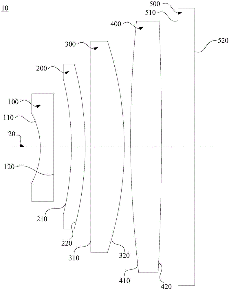
[0025] In order to facilitate the understanding of the present invention, the optical lens and the laser processing equipment with the optical lens will be more fully described below with reference to the relevant drawings. The preferred embodiments of the optical lens and the laser processing equipment with the optical lens are given in the accompanying drawings. However, the optical lens and the laser processing equipment with the optical lens can be implemented in many different forms, and are not limited to the embodiments described herein. On the contrary, the purpose of providing these embodiments is to make the disclosure of the optical lens and the laser processing equipment with the optical lens more thorough and comprehensive.

[0026] Unless otherwise defined, all technical and scientific terms used herein have the same meaning as commonly understood by one of ordinary skill in the technical field of the invention. The terms used herein in the specification of the ...


PUM


Abstract

The invention relates to an optical lens and a laser machining device with the optical lens. The optical lens comprises a first lens body, a second lens body, a third lens body and a fourth lens body which are sequentially distributed in the transmission direction of incident light beams. The first lens body is a double-concave negative lens, the second lens body is a meniscus positive lens, the third lens body is a flat-convex positive lens, and the fourth lens body is a double-convex positive lens. Substrates of the first lens body, the second lens body, the third lens body and the fourth lens body are made of high-temperature-resistant optical materials. According to the optical lens and the laser machining device with the optical lens, the substrates of the first lens body, the second lens body, the third lens body and the fourth lens body are made of the high-temperature-resistant optical materials, so the optical lens is applicable to the continuous high-power ultraviolet laser work environment, accordingly the problem that ultraviolet laser causes deformation of lens bodies in a lens can be effectively avoided, and fineness and definition of ultraviolet laser during workpiece machining are guaranteed.

Description

technical field [0001] The invention relates to the technical field of laser processing, in particular to an optical lens and laser processing equipment with the optical lens. Background technique [0002] Due to the short wavelength of the ultraviolet laser and the small radius of the focused spot, and the small diffuse spot and high resolution of the ultraviolet laser, the ultraviolet laser can be finely processed, so it is widely used in the processing of products. [0003] However, due to the short wavelength of the ultraviolet laser, the energy carried by the ultraviolet laser is larger than other types of lasers under the same power, which easily causes the lens in the lens to deform. For example, UV lasers change the radius of curvature of the lens, which affects the focal length of the entire lens. Especially when the lens is used in a continuous high-power ultraviolet laser working environment, some areas in the center of the lens will be continuously irradiated by...

Claims


Application Information

Patent Timeline
Patent Type & Authority Applications(China)
IPC IPC(8): G02B13/00G02B13/14
CPCG02B13/004G02B13/14
Inventor 李珊彭金明周朝明高云峰
Owner HANS LASER TECH IND GRP CO LTD
Why Eureka
Try Eureka