Multi-layer sealing ball valve for rail transit

A multi-layer sealing, rail transit technology, applied in valve details, valve device, valve shell structure, etc., can solve the problems of easy sealing performance to be affected by temperature changes, easy attenuation of installation torque, complex structure, etc., to reduce cleaning and maintenance. Cost, prevent destructive deformation, reduce leakage effect

Pending Publication Date: 2022-01-11
HUNAN LIANCHENG TRACK EQUIP CO LTD
View PDF2 Cites 0 Cited by
  • Summary
  • Abstract
  • Description
  • Claims
  • Application Information

AI Technical Summary

Problems solved by technology

[0005] The current welded ball valve has the following technical disadvantages: a single-layer or double-layer PTFE sealing structure is used between the valve body and the valve cover, and the sealing performance is easily affected by temperature changes; the single-layer or double-layer sealing structure is used between the valve stem and the valve body structure, the reliability is not strong; the valve body and the valve cover are softly connected, and the installation torque is easy to attenuate; the opening and closing degree of the handle is easily affected by the installation torque between the valve body and the valve cover
But this invention must be provided with a notch groove on the connection angle, and a plastic sealing ring and an elastic sealing ring that are in contact with the sphere and sealed with the sphere are installed in the notch groove, and the elastic sealing ring is correspondingly pressed on the top of the plastic sealing ring. See the structure diagram It can be found that the structure is complex and only has two layers

Method used


Image

  • Multi-layer sealing ball valve for rail transit
  • Multi-layer sealing ball valve for rail transit

Examples


Embodiment 1

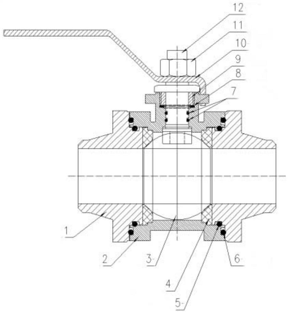
[0032] Such as figure 1 As shown, the present invention adopts the following technical solutions to realize: a welded ball valve with a multi-layer sealing structure used in the field of rail transit, consisting of a valve cover 1, a valve body 2, a ball 3, a gasket 4, a valve stem 12, and a valve stem Nut 11, handle 10, seal and other fasteners. The valve body 2 is located at the upper and lower ends of the welded ball valve. The valve body 2 is in sealing connection with the valve cover 1 and the valve stem 12. The valve stem 12 is set in the middle of the upper valve cover 1. The handle 10 is installed on the valve stem 12 and fixed with the valve stem nut 11. . Seals and fasteners include radial O-rings 5 ​​on the bonnet, axial O-rings 6 on the valve body, radial O-rings 7 on the valve stem, and composite gaskets 8 on the valve body. In this embodiment, as a preferred implementation manner, the handle and the valve stem are fixed by a valve stem nut, which can be disasse...


PUM


Abstract

The invention relates to a multi-layer sealing ball valve for rail transit. The multi-layer sealing ball valve comprises a ball body, valve bodies arranged at the upper end and the lower end of the ball body, upper and lower valve covers arranged between the ball body and the valve bodies, a valve rod penetrating through the middle of the upper valve cover, and a handle fixed to the valve rod; multi-layer sealing structures are arranged between the valve covers and the valve bodies; multi-layer sealing structures are arranged between the valve rod and the valve bodies; the valve bodies are of a sinking table type structure, and sealing gaskets for sealing through extrusion of boss type structures on the valve covers are arranged on sinking tables; and hard-connected limiting structures are arranged between the valve covers and the valve bodies. By adopting the multi-layer sealing structures, the ball valve is not prone to leakage due to the change of environment or medium temperature, the reliability of the sealing structure at the valve rod of the ball valve is improved, the valve rod does not leak when the ball valve handle is frequently opened and closed, and the influence of mounting torsion can be avoided.

Description

technical field [0001] The invention relates to the technical field of valves, in particular to a welded ball valve with a multi-layer sealing structure used in the rail transit field. Background technique [0002] The ball valve was born in the 1950s. With the rapid development of science and technology, the continuous improvement of production technology and product structure, it has rapidly developed into a major valve category in just 40 years. Ball valves are mainly used in pipelines to cut off, distribute and change the flow direction of media. [0003] Welded ball valves currently used in the rail transit industry on the market are composed of bonnets, valve bodies, balls, valve stems, handles, seals and other fasteners, and are used to adjust the medium flow of the cooling circuit or cut off the cooling circuit. Welded at both ends of the pipeline filter, when the traction cooling system cleans the filter, the welding ball valve at both ends of the filter needs to b...

Claims


Application Information

Patent Timeline
Patent Type & Authority Applications(China)
IPC IPC(8): F16K5/06F16K27/06F16K27/08F16K31/60
CPCF16K5/06F16K5/0663F16K5/0689F16K5/0694F16K5/0668F16K27/067F16K27/08F16K31/60
Inventor 谭志雄吴凯栾烨苏义刚
Owner HUNAN LIANCHENG TRACK EQUIP CO LTD
Why Eureka
Try Eureka