Check valve for protecting valve element

A technology of check valve and protection valve, which is applied in the direction of the valve's fluid energy absorption device, lift valve, valve details, etc., which can solve the damage of the valve core and seat, affect the flow rate of fluid in the pipeline, and the large impact force of the check valve and other issues to achieve the effect of avoiding impact

Inactive Publication Date: 2022-01-11
高琰
View PDF0 Cites 0 Cited by
  • Summary
  • Abstract
  • Description
  • Claims
  • Application Information

AI Technical Summary

Problems solved by technology

[0003] However, the existing pressure check valve still has the following deficiencies in the actual working process: First, because the traditional pressure check valve limits the position of the valve stem through the elastic connecting piece, it will only stop when the valve core is under a certain pressure. When the movement occurs, the spool will slowly move up and gradually open the valve. However, in some pipelines with low fluid pressure, due to the low fluid pressure, the pressure check valve can only open a small gap, which affects the pipeline. Therefore, it is necessary to set a check valve that will not open the valve core until the pressure reaches a predetermined value, and the valve core can be fully opened when the pressure reaches a predetermined value; at the same time, the traditional check valve There is a large impact force every time it is closed, which causes the sealing surface (usually a conical surface) at the lower part of the valve core to frequently impact the valve seat and cause damage to the valve core or valve seat, resulting in valve leakage, requiring frequent maintenance or replacement

Method used


Image

  • Check valve for protecting valve element
  • Check valve for protecting valve element
  • Check valve for protecting valve element

Examples


Embodiment Construction

[0018] Next, the technical solutions in the embodiments of the present invention will be described in connection with the drawings of the embodiments of the present invention, and it is understood that the described embodiments are merely the embodiments of the present invention, not all of the embodiments. Based on the embodiments of the present invention, all other embodiments obtained by those of ordinary skill in the art are in the range of the present invention without making creative labor premise.

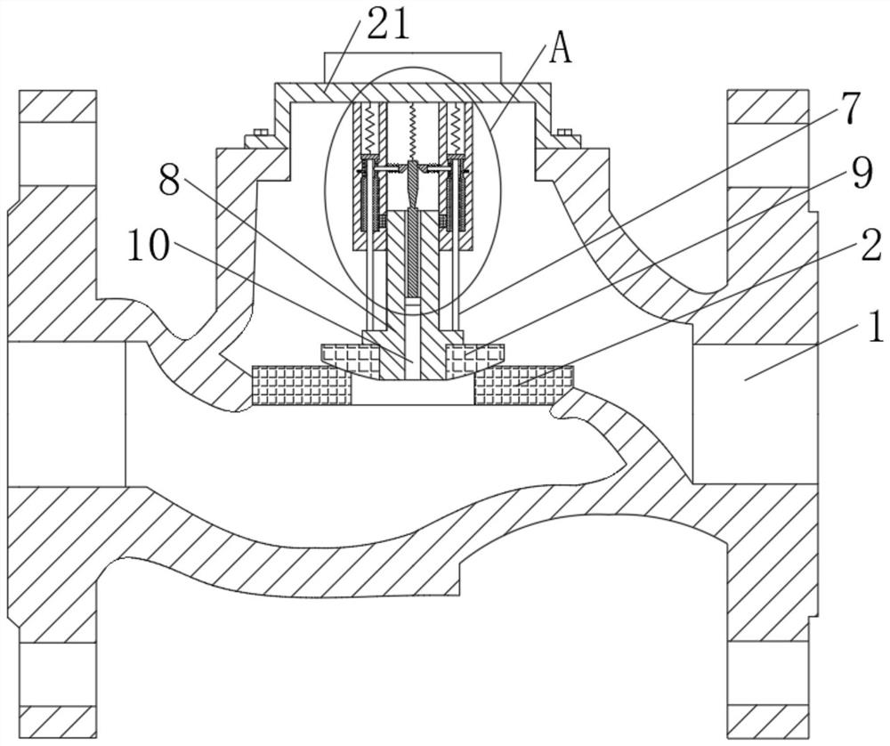
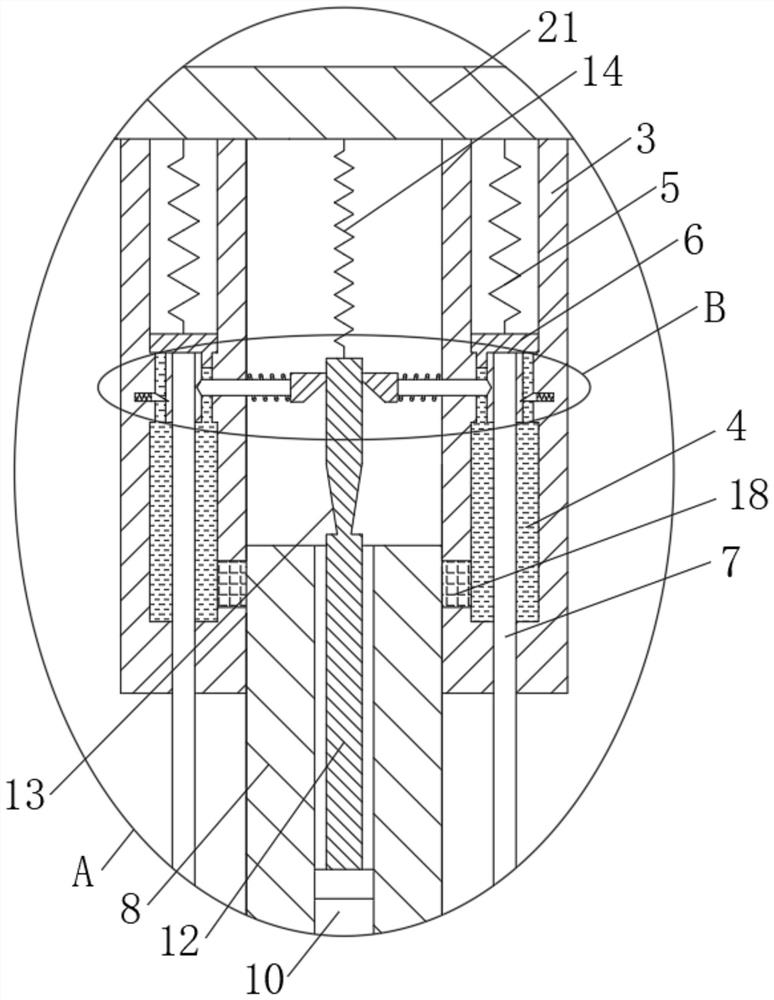
[0019] See figure 1 , figure 2 , Figure 4 A check valve for protecting the spool, including the valve body 1, the inner fixed mounting of the valve body 1, and the upper end of the valve body 1 is fixedly connected to the upper end cover 21, and the bottom cover 21 is fixedly connected to a sleeve 3, the inside of the bottom end of the sleeve 3 is opened, and the cavity 4 is filled with a hydraulic oil, and the inside of the upper end of the sleeve 3 is provided with four sets o...


PUM


Abstract

The invention relates to the technical field of pipeline valves, and discloses a check valve for protecting a valve element. The check valve comprises a valve body, a valve seat is fixedly mounted in the valve body, the upper end of the valve body is fixedly connected with an upper end cover, and the bottom of the upper end cover is fixedly connected with a sleeve. Through the arrangement of a sleeve, a connecting pipe, a rubber ring and a valve rod, when fluid in a pipeline is static, a movable rod rapidly descends to return to the original position, all ejector rods are ejected into a three-way pipe again through all limiting blocks, the three-way pipe is cut off, hydraulic oil in the bottom space of a piston can gradually enter a cavity through the connecting pipe in the reset process of a supporting spring, and the rubber ring is extruded to gradually expand towards the outer side of the cavity, the larger the expansion amount of the rubber ring is, the larger the friction force between the rubber ring and the side wall of the valve rod is, and therefore in the process that the valve element rubber makes contact with the valve seat, the speed is slower and slower, the valve element rubber makes contact with the valve seat slowly, the valve is closed, and the valve element and the valve seat can be protected.

Description

Technical field [0001] The present invention relates to the field of pipeline valve, in particular a check valve for protecting the spool. Background technique [0002] The check valve is a valve that refers to the closure of the circular flap and generates the weight of the weight and the medium pressure to block the media backflow, which is an automatic valve, also known as the counterpart, one-way valve or isolation valve. The flap movement is divided into a lifting and rotor, wherein the application of the decreased pressure check valve is particularly extensive. [0003] The existing pressure check valve has the following shortcomings in the actual operation: First, since the conventional pressure check valve is limited by the elastic connector to limit the valve stem, only when the spool is subject to a certain pressure When moving, the spool will slow down, gradually open the valve, and in a pipe in some fluid pressure, due to the small fluid pressure, the pressure type ch...

Claims


Application Information

Patent Timeline
Patent Type & Authority Applications(China)
IPC IPC(8): F16K15/02F16K1/32F16K1/36F16K47/00
CPCF16K15/02F16K1/32F16K1/36F16K47/00
Inventor 高琰
Owner 高琰
Why Eureka
Try Eureka