Roof mounting structure for photovoltaic power generation device

An installation structure and photovoltaic power generation technology, applied in the field of solar energy, can solve problems such as difficulty in installing solar panels, and achieve the effect of preventing falling off and improving stability

Pending Publication Date: 2022-01-11
HEFEI LISTEN NEW ENERGY TECH
0 Cites 0 Cited by

AI-Extracted Technical Summary

Problems solved by technology

[0004] The object of the present invention is to provide a roof installation structure for a photovoltaic power generation device. The installation frame is connected to the top plate, the clamp assembly is connected ...

Method used

A specific application of the present embodiment is: when the present invention is installed, the top plate 5 is placed on the ridge of the roof, and fixed by the counterweight 56, the installation frame 1 is laid obliquely on the roof slope, and the solar panel passes through the first The slide block 4 is fixedly installed on the mounting frame 1, and the clamping assembly 3 is clamped and fixed to the tiles by bolts, thereby further improving the stability of the mounting frame 1. The device is easy to install and has a stable structure.
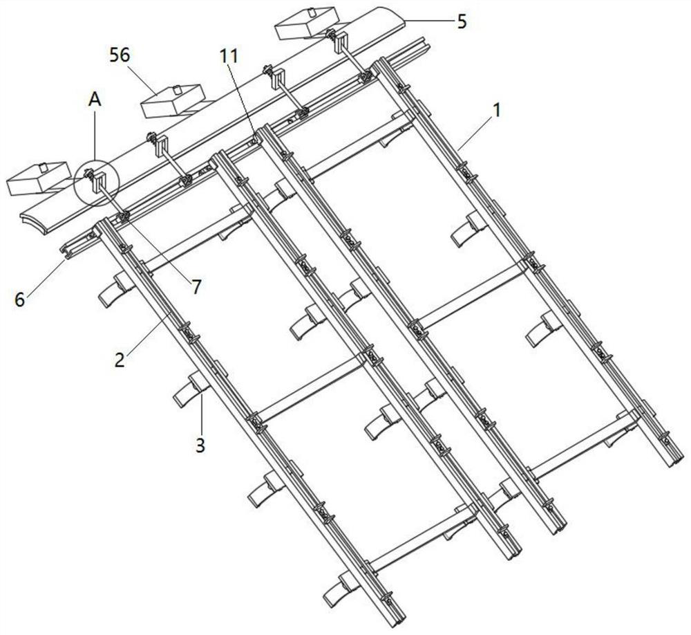
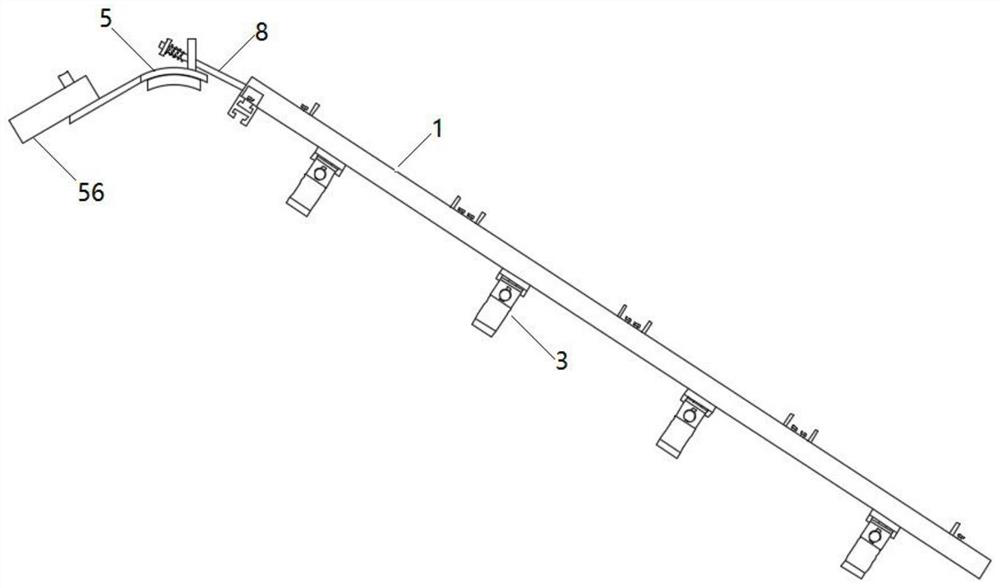
Please refer to shown in Fig. 1-3, the present invention is a kind of roof mounting structure for photovoltaic power generation device, comprises a plurality of mounting frames 1 for installing the rectangular frame shape structure of solar panel; Mounting frame 1 One end of the two guide rails 6 is fixedly connected to each other. The second guide rail 6 is connected with a top plate 5 for installation on the main ridge of the roof. The top plate 5 and the second guide rail 6 are fixedly connected by a plurality of connecting rods 8. The top plate 5 is far away from the One side of the second guide rail 6 is provided with a plurality of support plates 54, and the support plates 54 are connected with counterweights 56. By the pulling force of the counterweights 56 in the opposite direction, the mounting frame is fixed, and the second guide rail 6 is slidably connected. There are a plurality of second sliders 7, one end of the connecting rod 8 is hinged with the second slider 7, and the top plate 5 is fixedly connected with a connecting block 52 corresponding to the connecting rod 8 one by one, and the connecting block 52 is provided with the connecting rod 8. Cooperate with the connecting hole 53 in ...

Abstract

The invention discloses a roof mounting structure for a photovoltaic power generation device, and relates to the technical field of solar energy. The roof mounting structure comprises a plurality of mounting frames, wherein the mounting frame comprises a pair of first guide rails, the two first guide rails are fixedly connected through a connecting plate, a plurality of pairs of first sliding blocks are connected to the first guide rails in a sliding mode, the solar cell panels are fixed between every two adjacent first sliding blocks, and baffles are fixedly connected to the first sliding blocks; one ends of the mounting frames are fixedly connected through a second guide rail, a top plate used for being installed on a main ridge of a roof is connected to the second guide rail, the top plate and the second guide rail are fixedly connected through a plurality of connecting rods, a plurality of supporting plates are arranged on the side, which is away from the second guide rail, of the top plate, and balancing weights are connected to the supporting plates. The mounting frames are connected with the top plate, the clamping assembly is connected to the mounting frames, the balancing weights are connected to the top plate, and the problem that an existing roof solar cell panel is difficult to mount is solved.

Application Domain

Photovoltaic supportsRoof covering using slabs/sheets +3

Technology Topic

EngineeringStructural engineering +4

Image

  • Roof mounting structure for photovoltaic power generation device
  • Roof mounting structure for photovoltaic power generation device
  • Roof mounting structure for photovoltaic power generation device

Examples

  • Experimental program(1)

Example Embodiment

[0030] Next, the technical solutions in the embodiments of the present invention will be described in connection with the drawings of the embodiments of the present invention, and it is understood that the described embodiments are merely the embodiments of the present invention, not all of the embodiments. Based on the embodiments in the present invention, those of ordinary skill in the art will belong to the scope of the present invention without all other embodiments obtained in the preparation of creative labor.
[0031] In the description of the present invention, it is to be understood that the terms "top", "upper", "lower", "bottom", "top", "in", "within", "four weeks" The orientation or positional relationship is intended to facilitate the description of the present invention and simplified description, rather than indicating or implying that the component or element must have a particular orientation, and therefore is not understood to limit the invention.
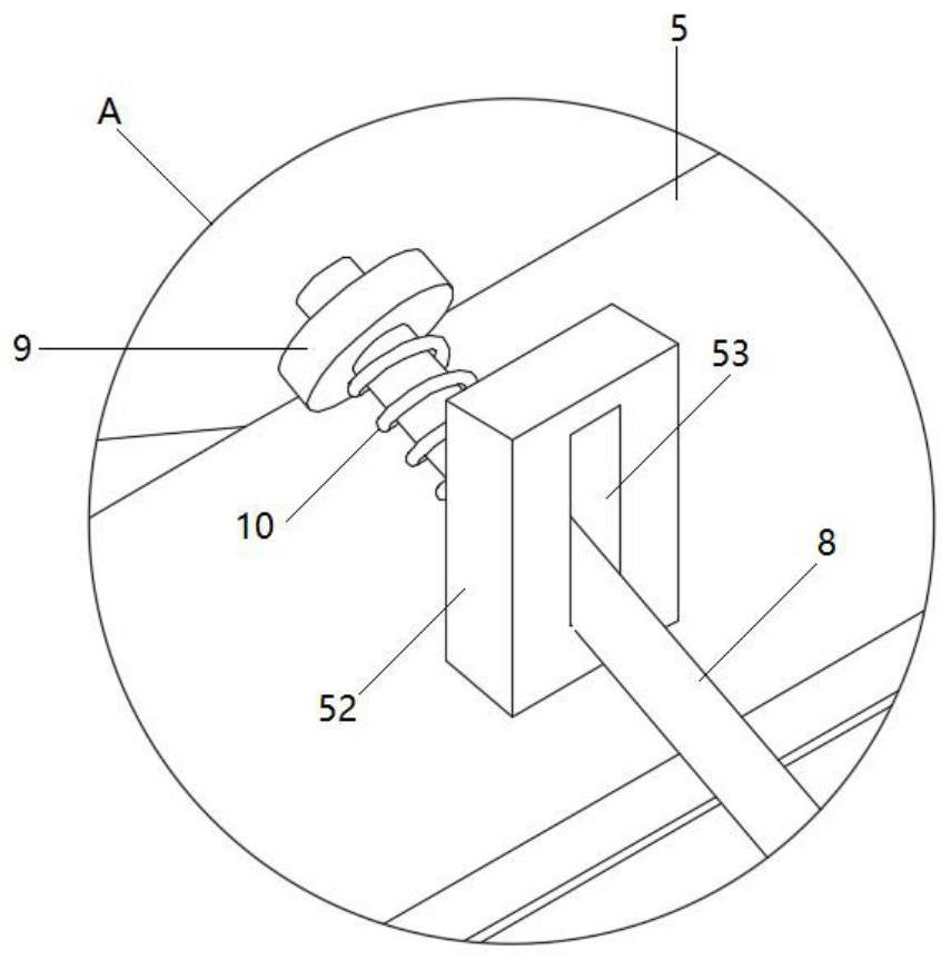
[0032] See Figure 1-3 As shown, the present invention is a roof mounting structure for a photovoltaic power generation device comprising a plurality of mounting frames 1 for mounting a rectangular frame of the solar panel; one end of the mounting frame 1 is fixed by the second rail 6 Connecting, the second rail 6 is connected to the top plate 5 for mounting at the ridge of the roof, and the top plate 5 is fixed to the second rail 8, and the top plate 5 is located away from the side of the second guide rail 6. The plurality of branch plate 54, the branch plate 54 is connected to the weight block 56, and the mounting frame 56 is fixed by the weighting block 56, and the mounting frame is fixed, and there is a plurality of second sliding blocks 7 on the second rail 6. One end of the connecting rod 8 is hinged from the second slider 7, and the top plate 5 is fixed to the connecting block 52 corresponding to the connecting rod 8, and the connecting block 52 is provided with a strip-shaped connection hole 53 with the connecting rod 8. One end of the connecting rod 8 is threaded and connected to a block 9, and a spring 10 is provided between the block 9 and the connecting block 52, and the spring 10 is sleeved on the connecting rod 8, which is involved in the mounting frame by the gravity of the weight block. The role prevents the mounting rack from falling, and the spring acts as a shock absorption.
[0033] See Figure 4-6 As shown, the mounting frame 1 includes a pair of first rail 2, the first rail 2 is the same, and the two first rails 2 are fixed by the connecting plate 21, and the stability of the mounting frame is further improved. The lower surface of the first guide rail 2 is fixedly connected to the clamp assembly 3 for fixing on the roof tile, and there is a multi-pair of first sliding blocks 4 on the first rail 2, and the solar panel is fixed in the neighbor two first. Between the slider 4, the first slider 4 is fixedly coupled to the first rail 2 by the fastening bolt 42, and the first slider 4 is fixed to the block 41, and the baffle 41 is fixed on both sides of the solar panel.
[0034] Wherein, the first rail 2 is fixedly coupled to the second rail 6 through a pair of clamps 11, and the block 11 is slidable with the second rail 6, and the block 11 is fixed to the first rail 2 side by a bolt.
[0035] See Figure 5 As shown, the clamp assembly 3 includes a connecting seat 31, the connecting seat 31 and the first rail 2 are fixed by a bolt, and the lower end of the connecting seat 31 is rotatable with a pair of splints 32, and the two-pinch plate 32 is fixed by the bolt, and the splint 32 is provided There is a strip hole 34 that is coupled to the bolt, securing the two splint 32 by bolts, the pinch plate 32 is clamped, wherein the pinch plate 32 includes a vertical plate 321 and a curved plate 322, and the vertical plate 321 rotates. Connecting, the lower end of the curved plate 322 is provided with a raised clamping portion 323, and the clamping portion 323 is clamped to the side sides of the tile 322, and the inner surface of the curved plate 322 is fixedly connected to the bubble pad 33 bonded with the surface of the roof tile. To prevent damage to the tile, and increase the contact area of ​​the tile panel 32, improve the support of the tile.
[0036] See Figure 7 The top plate 5 is an arcuate plate with the roof positive ridge. The top plate 5 is placed above the nij, the top plate 5 is fixed to the elastic pad 51, and the bracket 54 is fixedly connected to the lane 55, and the weight block 56 Hanging on the ladle 55 is convenient to assemble.
[0037] A particular application of the present embodiment is: When the present invention is mounted, the top plate 5 is placed at the ridge of the roof and is fixed by the weight block 56, and the mounting frame 1 is tilted, and the solar panel is passed through the first slider 4. The mounting frame 1 is fixed to the mounting frame 1, and the clamping assembly 3 is fixed by the bolt, further improve the stability of the mounting frame 1, the device is simple, and the structure is stabilized.
[0038]In the description of the present specification, a description of the reference terms "an embodiment", "Example", "Specific Examples", etc. One embodiment or in the example. In the present specification, the meaning of the above term is not necessarily referred to as the same embodiments or examples. Moreover, the specific features, structures, materials or features described may be combined in any one or more embodiments or examples.
[0039] The preferred embodiments of the invention disclosed above are only used to help illustrate the invention. The preferred embodiment does not detail all details, nor does not limit the embodiments of the invention. Obviously, according to the content of this specification, many modifications and changes can be made. The present specification is selected and specifically described, in order to better explain the principles and practical applications of the present invention, so that those skilled in the art can understand and utilize the present invention well. The present invention is limited only by the claims and the entire range and equivalents.

PUM

no PUM

Description & Claims & Application Information

We can also present the details of the Description, Claims and Application information to help users get a comprehensive understanding of the technical details of the patent, such as background art, summary of invention, brief description of drawings, description of embodiments, and other original content. On the other hand, users can also determine the specific scope of protection of the technology through the list of claims; as well as understand the changes in the life cycle of the technology with the presentation of the patent timeline. Login to view more.

Similar technology patents

Self-propelled crane for building construction

InactiveCN111252659Aprevent internal deformationPrevent falling off
Owner:吴虎群

One-way clutch

InactiveCN101451581APrevent falling offlow cost
Owner:TOK BEARING CO LTD

Control device for preventing spool equipment cable falling

InactiveCN103950785APrevent falling offProtect cables and equipment
Owner:SHANXI TAIGANG STAINLESS STEEL CO LTD

Classification and recommendation of technical efficacy words

  • Improve stability
  • Prevent falling off

Silicon/carbon nano composite fiber and application thereof

InactiveCN106129367APrevent falling offReduces deactivation and electrical contact loss
Owner:ZHEJIANG SCI-TECH UNIV
Why Eureka
Try Eureka