Flexible circuit board with external dustproof mechanism
A flexible circuit board and dust-proof technology, which is applied to the structural parts of electrical equipment, casing/cabinet/drawer parts, electrical equipment shell/cabinet/drawer, etc., can solve the problem of flexible circuit board burning, flexible circuit board Damage, affecting the working efficiency of flexible circuit boards, etc., to improve the heat dissipation effect and ensure normal use
- Summary
- Abstract
- Description
- Claims
- Application Information
AI Technical Summary
Problems solved by technology
Method used
Image

Examples
Embodiment 1
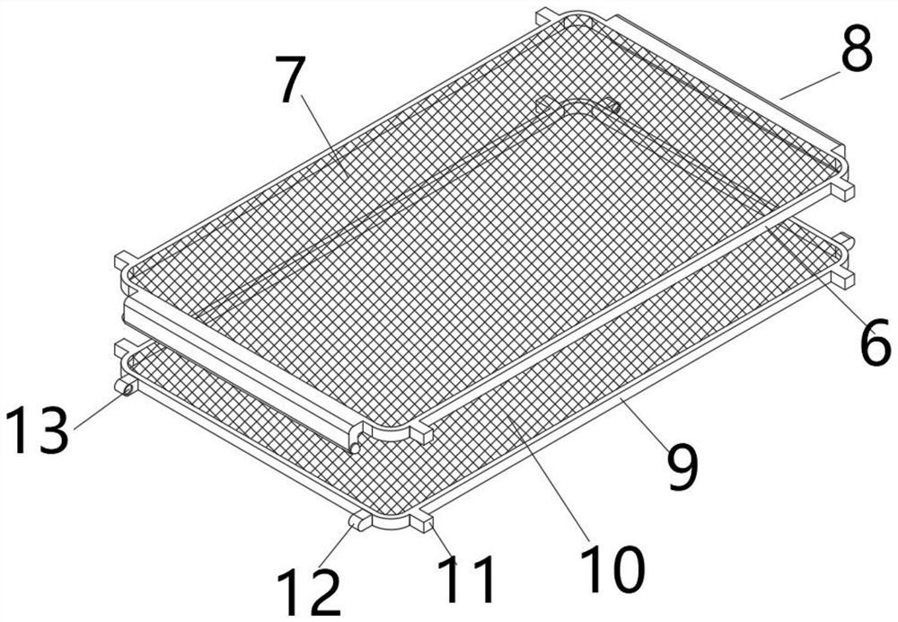
[0026] Such as image 3 As shown, in this embodiment, in order to prevent the dust in the air from adhering and accumulating on the upper surface and the lower surface of the flexible circuit board body 3, a first dustproof net 7 is fixedly installed in the frame wall of the upper dustproof frame 6, On the left and right side walls of the upper dust-proof frame 6, a group of symmetrical raised blocks 11 are respectively fixedly installed, and the second dust-proof net 10 is fixedly installed in the frame wall of the lower dust-proof frame 9, and the left and right sides of the lower dust-proof frame 9 A group of symmetrical raised blocks 11 are also fixedly installed on the side walls on both sides, and a group of symmetrical fixed blocks 12 are fixedly installed on the front and rear side walls of the lower dustproof frame 9 respectively, and the opposite sides of the symmetrical fixed blocks 12 There are card slots 13 respectively on the top, and the flexible circuit board b...
Embodiment 2
[0028] Such as Figure 4As shown, in this embodiment, in order to connect the upper dust-proof frame 6 and the lower dust-proof frame 9 together and sandwich the flexible circuit board body 3 between the upper dust-proof frame 6 and the lower dust-proof frame 9, the upper The front and rear side walls of the dust-proof frame 6 are respectively fixedly equipped with connecting plates 14, and the left and right side walls of the connecting plate 14 are respectively provided with spring grooves 15, and retaining rings 16 are fixedly installed in the notches of the spring grooves 15. One end of two compression springs 17 is respectively fixedly installed on the groove bottom of retaining ring 16, and the other end of compression spring 17 is fixedly installed with clamp block 18, and clamp block 18 passes retaining ring 16 and is positioned at draw-in groove 13, when going up When the dust-proof frame 6 and the following dust-proof frame 9 are combined, the blocks 18 protruding fr...
Embodiment 3
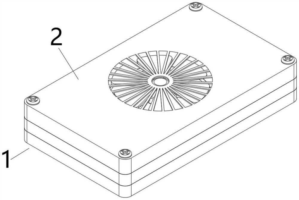
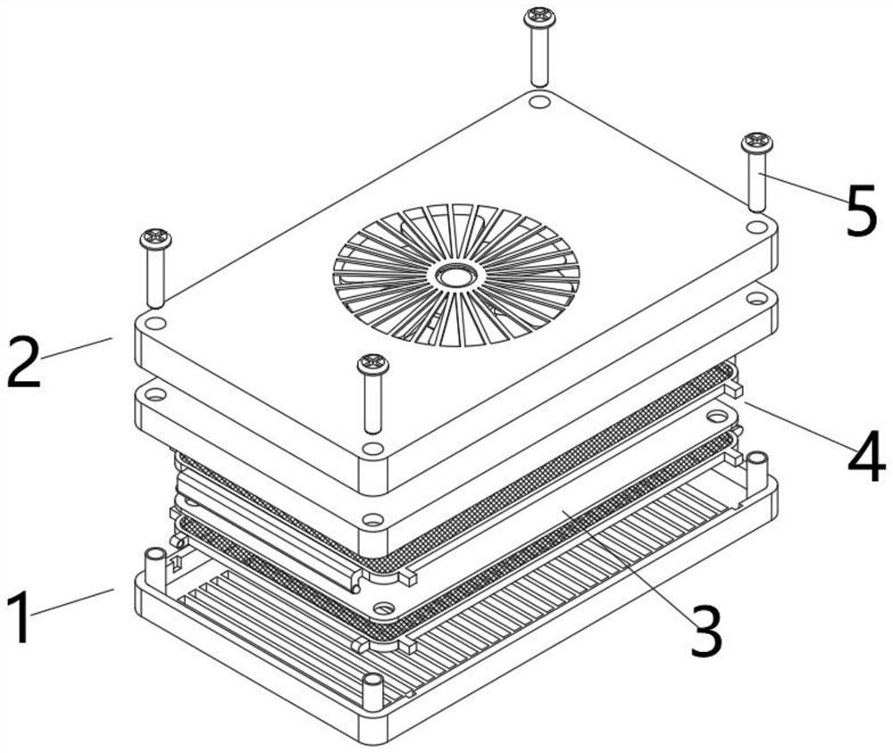
[0030] Such as Figure 5 As shown, in this embodiment, in order to protect the flexible circuit board body 3 and prevent the flexible circuit board body 3 from being damaged due to external factors, a heat dissipation opening 20 is opened at the center of the top surface of the upper protective case 19, and the upper The four corners of the top surface of the protective shell 19 are respectively provided with positioning holes 21, and the left and right side walls of the bottom surface of the upper protective shell 19 are respectively provided with grooves 24 corresponding to the raised blocks 11. The bottom surface is provided with several radiating grooves 23 in a row, and the side walls on the left and right sides of the top surface of the lower protective shell 22 are respectively provided with grooves 24 corresponding to the protruding blocks 11. The inner bottom surface of the lower protective shell 22 is Positioning posts 25 are respectively fixedly installed at the fou...
PUM
 Abstract
Description
Claims
Application Information
 - R&D
- Intellectual Property
- Life Sciences
- Materials
- Tech Scout
- Unparalleled Data Quality
- Higher Quality Content
- 60% Fewer Hallucinations
Browse by: Latest US Patents, China's latest patents, Technical Efficacy Thesaurus, Application Domain, Technology Topic, Popular Technical Reports.
© 2025 PatSnap. All rights reserved.Legal|Privacy policy|Modern Slavery Act Transparency Statement|Sitemap|About US| Contact US: help@patsnap.com