Full-electric driving platform power battery rapid reloading device and reloading method thereof
A power battery and electric drive technology, applied in electric power units, power units, electric vehicles, etc., can solve the problem of short driving range of electric drive chassis, and achieve short driving range, improve power performance, and facilitate quick replacement. the effect of
Pending Publication Date: 2022-01-14
BEIJING MECHANICAL EQUIP INST
0 Cites 0 Cited by
AI-Extracted Technical Summary
Problems solved by technology
[0005] In view of the above analysis, the embodiment of the present invention aims to provide a quick replacement device and replacement method for t...
Method used
Compared with the prior art, the present invention is by sequentially setting the first mushroom head lock block 13, the twist lock support assembly 3, the first fixed nut 14 and the first shift fork 16 on the central axis, on the one hand can The first turnlock assembly 8 and the second turnlock assembly are fixed on the vehicle body 25; on the other hand, the first shift fork 16 can be used to drive the first mushroom head lock block 13 to rotate in the corresponding mounting hole to realize The fast unlocking and locking of the installation frame assembly 1 of the power battery 2 and the electric twist lock unit 4 finally realizes the rapid replacement of the power battery 2 .
[0057] Compared with the prior art, the present invention adopts the concept of modularization, and the power battery 2 is arranged in the installation...
Abstract
The invention relates to an all-electric driving platform power battery quick reloading device and a reloading method thereof, belongs to the technical field of battery reloading devices, and solves a technical problem that the driving range of an existing electric driving chassis is short. The power battery quick reloading device comprises a mounting frame assembly, a spin lock supporting unit and an electric spin lock unit, wherein a power battery is arranged in the mounting frame assembly; the electric spin lock unit is fixed to a vehicle body through the spin lock supporting unit; the mounting frame assembly comprises a mounting frame; connecting seats are arranged on a lower surface of the mounting frame; and the electric spin lock unit is matched with the connecting seat to realize locking or unlocking of the mounting frame assembly and the vehicle body. The device is advantaged in that a problem that the driving range of an electric drive chassis is short is solved, and dynamic property of the electric drive chassis is improved.
Application Domain
Charging stationsElectric propulsion mounting +2
Technology Topic
Electric driveElectrical battery +3
Image
Examples
- Experimental program(2)
Example Embodiment
[0052] Example 1
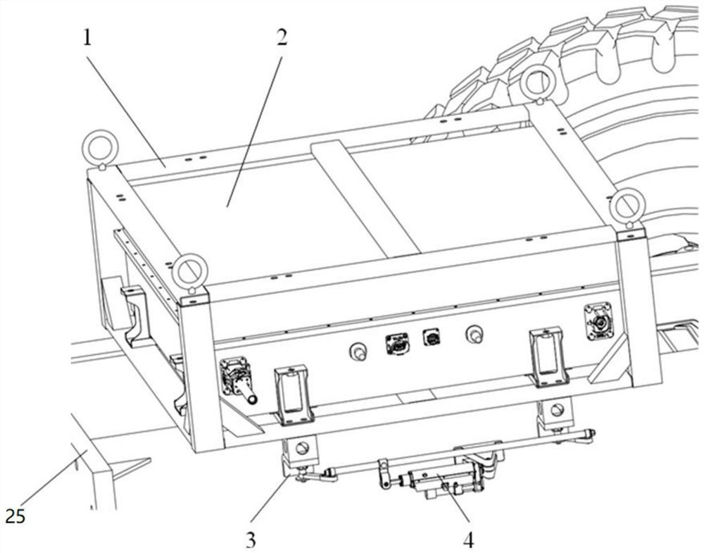
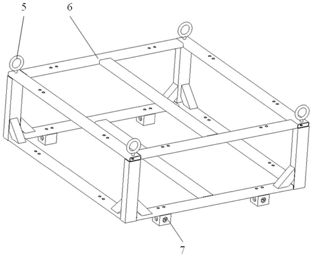
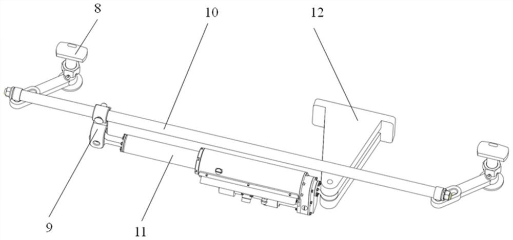
[0053] This embodiment provides a power battery for a full-electric drive platform, such as Figures 1 to 10 As shown, the power battery rapid reloading device includes a mounting frame assembly 1, a rotary lock support unit, and an electric spinning unit 4; a power battery 2 is provided in the mounting frame assembly 1; the electric spin lock unit 4 passes through a rotary lock support unit Fixed on the body 25; mounting frame assembly 1 includes mounting frame 6; the mounting frame 6 is provided with the same structure, two two corresponding settings, i.e., the first connecting seat 7, the second connecting seat, the first Three connecting seats and fourth connecting seat; the electric spinning unit 4 includes the same structure, corresponding to the first electric oscillatling mechanism, and the second electric stop mechanism.
[0054] Exemplarily, such as figure 1 As shown, the first electric oscillatling mechanism and the second electric stop mechanism are arranged in parallel to both sides of the mounting frame 6, accordingly, the four connecting holders are disposed on both sides of the mounting frame 6, and the two connecting holders are disposed in On one side of the mounting frame 6, the two connecting holders are disposed on the other side of the mounting frame 6, at this time, the two ends of the first electric oscill lock mechanism are locked with the first connecting seat 7 and the second connecting seat, namely the first The electric rotary lock mechanism is connected by the first connecting seat 7 and the second connecting seat and the mounting frame 6, and both ends of the second electric locking mechanism are connected to the third connecting seat and the fourth connecting seat, that is, the second electric locking mechanism passes through The third connecting holder and the fourth connecting seat are connected to the mounting frame 6; when the power battery 2 is required, the mounting frame assembly 1 and the electric splitting unit 4 are set to unlock state; when the power battery 2 is replaced, The mounting frame assembly 1 is set to a locked state with the electric spinning unit 4.
[0055] Illustratively, the power battery fast reloading device includes a mounting frame assembly 1, a rotary lock support unit, and an electric spinning unit 4; mounting frame assembly 1 includes a rectangular mounting frame 6, mounting frame 6 through various mounting plates Fixed together, the power battery 2 is disposed within the mounting frame 6, the power battery 2 and the mounting frame 6 are integrated or detachable; the four end portions of the lower surface of the mounting frame 6 are respectively provided A joint 7, the second connecting seat, the third connecting seat, and the fourth connecting seat; the mounting frame 6 is detachably connected by the first connecting seat 7 to the fourth connecting seat and the electric spinning unit 4; the electric rotary lock unit 4 passes The rotary lock support unit is fixed to the body 25, and the electric rotary lock unit 4 includes the same first electric stop mechanism and the second electric stop mechanism, wherein the two ends of the first electric oscill lock mechanism are respectively connected to the first connection. 7 and the second connecting seat lock connection, both ends of the second electrical lyl lock mechanism are locked with the third connecting seat and the fourth connecting seat, respectively.
[0056] When the power battery 2 is low, when the power battery 2 is required to be quickly reloaded, the first electric stop mechanism is arranged to unlock state between the first connecting mechanism and the first connecting seat 7 and the second connecting seat, the second electric lock lock The mechanism and the third connecting seat and the fourth connecting seat are also set to unlock state, at this time, the mounting frame assembly 1 and the electric splitter unit 4 are unlocked, and the frame assembly 1 and power battery 2 Lifting the floor supporting equipment power vehicle for charging, while lifting the full power battery 2 and the mounting frame assembly 1 on the power vehicle to the full-electric drive platform, the power battery 2 is switched, and the first electric rotation The lock mechanism is arranged between the locking mechanism and the second connecting seat, which is intended, and the second electric stop mechanism and the third connecting seat and the fourth connecting seat are also set to lock state, this When the mounting frame assembly 1 and the electric rotary lock unit 4 are locked, the power battery 2 is completed.
[0057] Compared with the prior art, the present invention adopts modular concept, and the power battery 2 is disposed in the mounting frame assembly 1, and the power battery 2 is made into a single module, and the first connective seat 7 to the fourth connection Generalization interface, easy to replace; the full-electric drive platform power battery 2 provided by the present invention is suitable for use in the short-lived mileage, the electric drive chassis having a long charging time, rapidly The power battery 2 is replaced, solve the problem of shorting the mileage of the electric drive, and improve its dynamic.
[0058] In order to achieve a switching between the first electric oscillatling mechanism and the second electric stop mechanism and the corresponding connection seat 7, a mounting hole is provided in the first connecting seat 7 to the fourth connection seat; The first electrical oscillatic lock mechanism and the second electric ignition mechanism include a first connecting shaft assembly 10, a first electrical cylinder 11, and a first rotary lock assembly having the same structure, and a second rotary lock assembly; The lock assembly 8 and the second rotary lock are respectively provided on both ends of the connecting shaft assembly, and the connecting shaft assembly is provided with a first lever assembly 9, and the first electro-cylinder 11 ends and the first chaler assembly. 9 fixedly connected, the other end is fixed to the electric cylinder fixed to the body 25; the first rotary lock assembly 8 and the second rotor lock assembly are unlocked with the mounting holes of the corresponding connecting seat 7.
[0059] Exemplarily, such as image 3 As shown, both the first connecting seat 7 to the fourth connecting holder are hollow shapes, and there is a rectangular mounting hole inside; the first electric oscillating mechanism and the second electric lock mechanism are the same, the first electric lock lock The mechanism includes a first connecting shaft assembly 10, a first electro-cylinder 11, and a second rotary lock assembly having the same structure, and the first rotary lock assembly 8 and the second rotary lock assembly are respectively set. At both ends of the first connecting shaft assembly 10, the first rotary lock assembly 8 and the second rotor lock assembly are slidable between the first connecting shaft assembly 10 and the first connecting shaft assembly 10 can be driven A spin lock assembly 8 and the second rotational lock assembly are rotated; a first lever assembly is provided on the first connecting shaft assembly 10, and one end of the first lever assembly 9 and the first electro-cylinder 11 is fixed. On the other hand, the other end of the first electrical cylinder 11 is fixed to the body 25 by the electric cylinder mounting bounce; it is necessary to explain that the mounting direction of the first electric cylinder 11 is parallel to the axial direction of the first connecting shaft assembly 10. When the first electrical cylinder 11 is telescopic, the first connecting shaft assembly 10 can be moved by the first pier shaft assembly 9, and since both ends of the first connecting shaft assembly 10 are respectively composed of the first rotary lock assembly 8 and the second rotary lock assembly slide to connect, thereby driving the first rotary lock assembly 8 and the second rotational lock assembly, and finally realize the first rotary lock assembly 8 and the second rotor lock assembly and corresponding connecting seat 7 Locking and unlocking of the inner mounting holes.
[0060] Compared with the prior art, the first electric cylinder 11 provided by the present invention via the first connecting shaft assembly 10 by the first lever assembly 9, which further causes the first connection shaft assembly 10 to drive the first rotary lock. The total 8 and the second rotary lock assembly are unlocked and locked with the mounting holes within the corresponding connecting seat 7 to achieve unlocking and locking between the installation frame assembly 1 and the electric spin assembly of the power cell 2, Finally, the fast-moving process of power battery 2 has solved the problem of shorting the mileage of the electric discharge, improved its dynamic.
[0061] In order to secure the electric rotary lock unit 4 on the body 25 and to ensure the unlocking and lock of the mounting frame assembly 1 and the electric rotary lock unit 4, the rotary lock support unit of the present invention includes a rotary lock support assembly 3; the first rotary lock The same structure is the same, the first rotary lock assembly 8 includes a first mushroom head lock block 13, the first fixing nut 14 and the first dial 16; the first mushroom head lock block 13, the rothelock The support assembly 3, the first fixing nut 14 and the first diagram 16 are sequentially disposed on the central axis, and the first mushroom head lock block 13 and the first dial 16 are fixed.
[0062] Specifically, the rotary lock support unit includes four structurally identical rotary lock support assemblies 3, and the set position of the rotary lock support assembly 3 corresponds to the set position of the first connecting seat 7 to the fourth connecting seat; Figure 4 , Figure 7 to 9 As shown, the first rotary lock assembly 8 and the second rotational lock assembly include the first mushroom head lock block 13, the first fixed nut 14 and the first dial 16, where Figure 7 to 9 As shown, the first mushroom head lock block 13, the rotary lock support assembly 3, the first fixing nut 14 and the first diagram 16 are sequentially disposed on the central axis, that is, the central axis sequentially passes through the first mushroom head lock block 13, Rotary lock support assembly 3, the first fixing nut 14 and the first dial 16, wherein the first fixing nut 14 is used to secure the rotary lock support assembly 3, avoiding the rotary lock support assembly 3 and the first mushroom head lock block There is a looseness between 13. It should be noted that the shape of the first mushroom head lock block 13 is seen Figure 4 The first mushroom head lock block 13 can pass through the mounting hole of the connecting seat 7, and when the first mushroom head lock block 13 is vertical, the first mushroom head lock block 13 is attached to the mounting hole, and then realizes electric The rotary lock unit 4 is locked with the mounting frame assembly 1.
[0063] Compared with the prior art, the present invention can be set in the central axis, and the first mushroom head lock block 13, the rotary lock support assembly 3, the first fixing nut 14 and the first dial 16 can be first The rotary lock assembly 8 and the second rotor lock assembly are fixed to the body 25; on the other hand, the first mushroom head lock block 13 can be rotated within the corresponding mushroom, to achieve power The mounting frame assembly of the battery 2 and the rapid unlocking and lock of the electric rotary lock unit 4, ultimately realizing the fast reload power battery 2.
[0064] In order to be able to drive the first dial 16, the first connecting axis assembly 10 of the present invention includes a first connecting shaft 24, and both ends of the first connecting shaft 24 have a structural first end and a second end, The first end and the second end portion include a second fixing nut 22 and a first slider 23; the first finifier 16 is located at one end of the central axis, and the first slider 23 is set in the first slide. Rail; the first electrical cylinder 11 passes through the first chaler assembly 9, and the first connecting shaft assembly 10 is further rotated in the mounting hole of the corresponding connecting seat 7 in the corresponding connection seat 7.
[0065] Specifically, such as Figure 6 to 8As shown, the first connecting axis assembly 10 includes a first connecting shaft 24, and both ends of the first connecting shaft 24 are the same first end and the second end, and the first end and the second end include the first end. The second fixing nut 22 and the slider are used to secure the slider on the first connecting shaft 24; the first finifier 16 is located at one end of the central axis, and the first slider 23 is Insert the first slide guide; under the thrust of the first electro-cylinder 11, the first lever assembly 9 has a first connection axis of the first connection shaft as the first connecting shaft assembly 10 of the first electrical cylinder 11. The first slider 23 of 10 is driven by means of a central axis around the first mushroom head lock block 13, and since the first mushroom 16 and the first mushroom head lock block 13 is fixed, Therefore, the first mushroom head lock block 13 can achieve a central axis rotation in the mounting hole under the telescopic movement of the first electric cylinder 11. When the first electrical cylinder 11 is extended, the first electric cylinder 11 is inaccessible to the first mushroom head lock block 13 and is parallel to the mounting hole, and the mounting hole frame assembly and the unlock of the electric rotary lock unit 4 are realized. When the electric cylinder is in a retracted state, the first mushroom head lock block 13 rotates 90 ° under the indirect drive of the first electro-cylinder 11, and the first mushroom head lock block 13 is perpendicular to the mounting hole, and the mounting hole assembly is achieved. The locking of the electric rotary lock unit 4 is locked.
[0066] In order to be able to use the first electric cylinder 11 to swing before and after the first connecting rod assembly, a first pin hole is provided on the first connecting shaft 24 of the present invention; the first lever assembly 9 includes a collar, the first link pin 18 The first pension 19 and the second connecting pin 20 are provided on the ferrule, and the collar sleeve is provided on the first connecting shaft 24 and the first link pin 18 passes through the first pin hole and the second pin. Hole; the first pier 19 is provided with a third pin hole, and the first electric cylinder 11 is provided with a fourth pin hole adjacent to the first end of the lever; the second connecting pin 20 passes through the third pin hole and the fourth pin hole. The first electrical cylinder 11 is fixed to the first pierge 19.
[0067] Specifically, such as Image 6 As shown, the first pin hole is provided at one end of the electric cylinder mounting bounce 12 on the first connecting shaft 24; Figure 5 As shown, the first lever assembly 9 includes a collar and a first branch of the collar integral shape, and the ferrule is disposed at the first pin hole of the first connecting shaft 24, i.e., the first pin hole. In the collar, a second pin hole is provided on the jacket, and after the first pin hole and the second pin hole are aligned, the first pin hole and the second pin hole are inserted by the first connecting pin 18, which in turn The first lever assembly 9 and the first connecting axis assembly are fixed together. A third pin hole is provided on the first diaphragir 19, and the first electrical cylinder 11 is located at one end of the electric cylinder steel mounting stock, and after the third pin hole and the fourth pin hole are aligned, the second The connecting pin 20 is inserted into the third pin hole and the fourth pin hole, thereby fixing the first lever assembly 9 with the first electric cylinder 11.
[0068] It is emphasized that when the power battery 2 needs to be replaced, the first electric cylinder 11 passes through the first lever assembly 9, and the first connecting axis assembly 10 has a first mushroom head lock of the first rotary lock assembly 8. 13 Turn 90 ° in the corresponding connecting seat 7, the first mushroom head lock block 13 is parallel with the mounting hole and passes from the mounting hole, and the mounting frame assembly 1 is arranged to unlock state; when the power battery 2 After the replacement, the first electrical cylinder 11 passes through the first lever assembly 9, the first connecting shaft assembly 10 drives the first mushroom head lock block 13 of the first rotary lock assembly 8 to penetrate the first connection 7 In the mounting hole, the mounting hole is rotated 90 °, and the first mushroom head lock block 13 is perpendicular to the mounting hole, the mounting frame assembly 1 is locked in a locked state.
[0069] In order to further fix the rotary lock support assembly 3, the first rotary lock assembly of the present invention further includes a first opening pin 15 through the central axis and a first at the bottom of the first finifier 16. The pad 17, the first open pin 15 is provided below the first fixing nut 14, and the first open pin 15 is used to reinforce the first fixing nut 14; the first pad 17 is fixed to the central axis, the first pad 17 is used Support the first finifier 16.
[0070] In order to secure the first connecting pin 18 and the second connecting pin 20, the first connecting pin 18 and the first connection pin 18 of the present invention are ensured by the first connecting pin 9 and the first electro-cylinder 11. Both the two connection pins are fixed by the second open pin 21.
[0071] In order to secure the rotary lock support assembly on the body 25, the rotary lock support assembly 3 includes a horizontal portion and a bending portion, the bending portion is fixed to the body 25; the horizontal portion is provided with a central hole, the horizontal portion passes through the center hole A first mushroom head lock block 13 and the first fixed nut 14 are set between the central axis.
[0072] In order to make it easy to hang the installation frame assembly 1, such as figure 1 and figure 2 As shown, the mounting frame 6 is provided with a hanging ring 5, and the hanging ring 5 is used to hang the mounting frame assembly 1 and the power battery 2.
[0073] Specifically, when the power battery 2 is required to replace the power battery 2, the four suspended ring 5 of the mounting frame assembly 1 is used, and the power battery 2 is lifted with the mounting frame assembly 1, at this time, The first mushroom head lock block 13 of the second oscillatic assembly 8 and the second spinner assembly is inserted from the mounting hole of the corresponding connecting seat 7, and the mounting frame assembly 1 is separated from the electric centers 4.
[0074] The present invention can facilitate the mounting frame assembly 1 and the power battery 2 to facilitate the fast replacement of the power battery 2 at the top of the mounting frame 6.
Example Embodiment
[0075] Example 2
[0076] This embodiment provides a power battery rapid replacement method of a full-electric drive platform, and a power battery of the full-electric drive platform provided in Example 1, when the power battery 2 is provided in the installation frame assembly 1 (Power Battery 2 is installed on the body 25), such as figure 1 As shown, the respective connecting holders of the mounting frame assembly 1 and the corresponding first rotary lock assembly are between the locking state, at which time the first mushroom head lock block 13 and the corresponding connecting seat 7 The mounting hole is perpendicular, and the first electric cylinder 11 is in a retracted state, such as Figure 7 Indicated. When the power battery 2 is low, the power battery 2 is quickly rehabilized, and the method includes the following steps:
[0077] Step 1, start the electric ignition unit 4, the first electric cylinder 11 projects, the first lever assembly 9 drives the first connection shaft assembly 10 forward, the first connecting shaft assembly 10 of the first slider 23 The first dial 16 of the first rotary lock assembly 8 rotates about the central axis of the first mushroom head lock block 13, the first mushroom head lock block 13 rotates 90 ° with the first dial 16, at this time, the first mushroom The head lock block 13 is a horizontal state, such as the mounting hole on the connecting seat 7 of the mounting frame assembly 1, such as Figure 8 As shown, unlocking;
[0078] Step 2, using the four hanging ring 5 of the mounting frame assembly 1 to hang the power battery 2 and the mounting frame assembly 1; the first mushroom of the first rotary lock assembly 8 and the second rotary lock assembly The head lock block 13 passes through the mounting holes of each connecting seat of the mounting frame assembly, such as Figure 9 As shown, the power battery 2 and the mounting frame assembly 1 are separated from the rotary lock support assembly;
[0079] Step 3, lifting the power battery 2 and the mounting frame assembly 1 to the ground supporting equipment power vehicle for charging; simultaneously lifting the backup power battery 2 and the mounting frame assembly 1 of the power vehicle to the full power drive platform ,like Figure 10 Indicated;
[0080] Step 4, the first mushroom head lock block 13 of the first rotary lock assembly 8 and the mushroom head lock block 13 from the mounting frame of the mounting frame assembly 1, such as Figure 9 The showing, then falling on the center of the spin lock, such as Figure 8 Indicated;
[0081] Step 5, the first electric cylinder 11 that activates the electric ignition unit 4 is retracted, the first lever assembly 9 drives the first connection shaft assembly 10 backward swing, the first connecting shaft assembly 10 of the first slider 23 The first dial 16 of the first rotary lock assembly 8 rotates about the central axis of the first mushroom head lock block 13, the first mushroom head lock block 13 rotates 90 ° with the first dial 16, at this time, the first mushroom The head lock block 13 is perpendicular to the mounting holes on each connecting seat of the mounting frame assembly 1, such as Figure 7 As shown, lock, complete the dressing, such as figure 1 Indicated.
PUM


Description & Claims & Application Information
We can also present the details of the Description, Claims and Application information to help users get a comprehensive understanding of the technical details of the patent, such as background art, summary of invention, brief description of drawings, description of embodiments, and other original content. On the other hand, users can also determine the specific scope of protection of the technology through the list of claims; as well as understand the changes in the life cycle of the technology with the presentation of the patent timeline. Login to view more.
Similar technology patents
Exhaust manifold device and front end cover processing method
ActiveCN104975926AReduce exhaust resistanceImprove power
Owner:BRILLIANCE AUTO
Method for preparing high-quality fuel oil blended with alcohol-containing fuel
ActiveCN104194845AImprove running performanceImprove power
Owner:GUIZHOU QIANSHENG NEW ENERGY IND
Electric vehicle four-wheel-drive torque distribution method and system and vehicle
ActiveCN113320400AImprove powerImprove driving comfort
Owner:CHONGQING CHANGAN AUTOMOBILE CO LTD +1
Method for controlling air inlet throttle valve, control device, electronic control unit and vehicle
ActiveCN113531113AIncrease exhaust temperatureImprove power
Owner:WEICHAI POWER CO LTD
Control method and deviceof vehicle air treatment unit, equipment and vehicle
Owner:FAW JIEFANG AUTOMOTIVE CO