Offshore garbage collector

A garbage collection and garbage technology, which is used in special-purpose ships, open water surface cleaning, load handling devices, etc., can solve the problems of cutting, huge cost, single, etc., and achieve the effect of reducing volume and cost.

Pending Publication Date: 2022-01-14
CHONGQING UNIV
View PDF0 Cites 2 Cited by
  • Summary
  • Abstract
  • Description
  • Claims
  • Application Information

AI Technical Summary

Problems solved by technology

Under a certain power, the U-shaped net moves forward to make the garbage flow into the bottom along the U-shaped wall. When it reaches a certain limit, it is collected manually, but to a certain extent, it can control the inflow of garbage artificially. However, this design is relatively simple and traditional, and it requires a huge amount of money to use manpower, and because the U-shaped net is easy to be cut by sharp objects on the sea when it is in use, it is easy to cause the replacement of the U-shaped net to be very difficult. Frequent, costly expenditure

Method used


Image

  • Offshore garbage collector
  • Offshore garbage collector
  • Offshore garbage collector

Examples


Embodiment 1

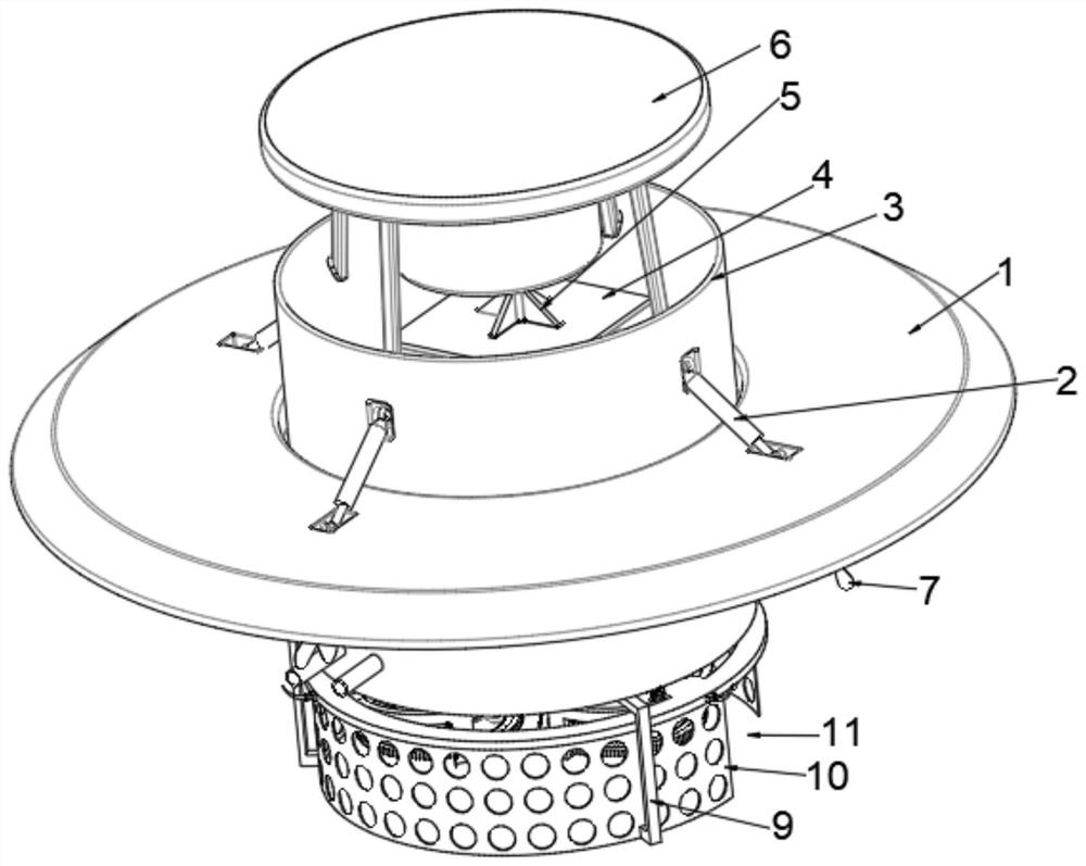
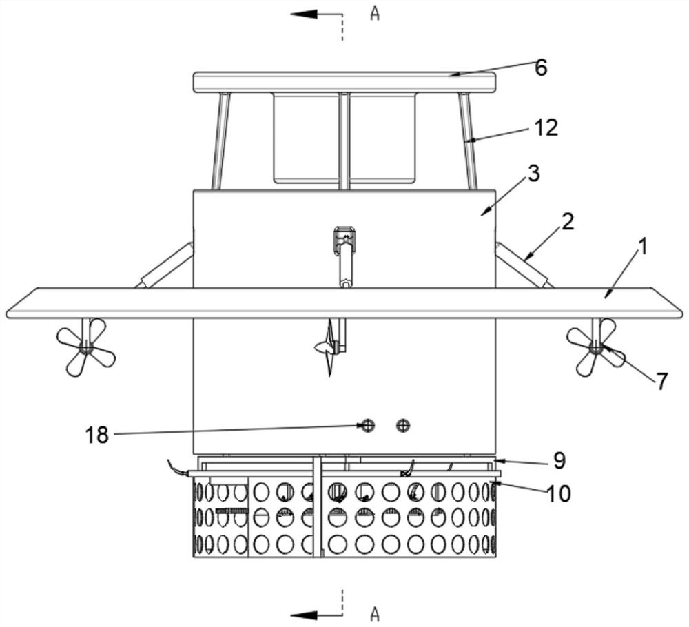
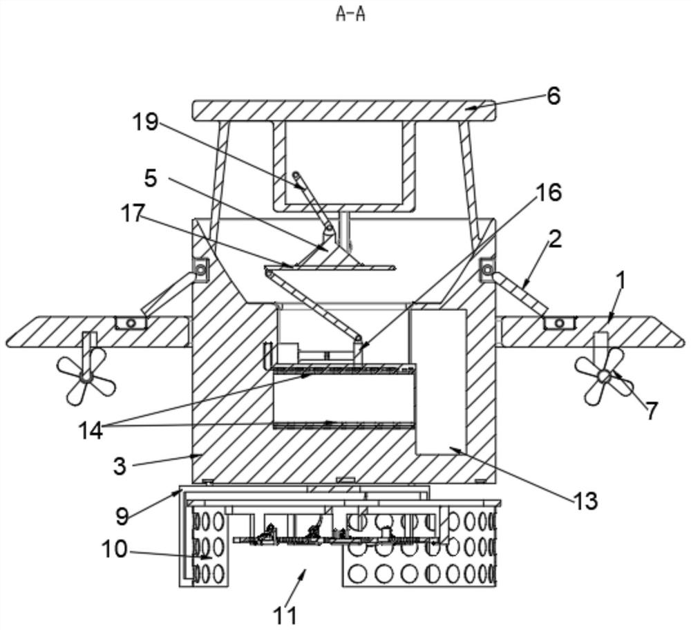
[0030] see Figure 1-Figure 4 , the present invention provides a technical solution: a marine garbage collector, comprising a floating plate 1, the bottom of the floating plate 1 is equidistantly fixed with propellers 7, and the top of the floating plate 1 is movably installed with a first balance bar 2, The inside of the floating plate 1 is penetrated with a collection box 3, and the top of the collection box 3 is provided with a feed inlet, and a support rod 12 is movably installed inside the feed inlet, and a top plate 6 is movably installed on the top of the adjacent support rod 12, and the collection box 3 is provided with a compression bin, a water storage bin and a compressed garbage removal bin 13, a water pump is fixedly installed inside the collection box, a garbage compression mechanism is arranged inside the compression bin, and a porous filter layer 14 is fixedly installed, the compression bin, the water storage bin and the The compressed garbage removal bins 13 c...

Embodiment 2

[0037] see figure 1 , figure 2 , Figure 5 , Figure 6 , the present invention provides a technical solution: a marine garbage collector, comprising a floating plate 1, the bottom of the floating plate 1 is equidistantly fixed with propellers 7, and the top of the floating plate 1 is movably installed with a first balance bar 2, The inside of the floating plate 1 is penetrated with a collection box 3, and the top of the collection box 3 is provided with a feed inlet, and a support rod 12 is movably installed inside the feed inlet, and a top plate 6 is movably installed on the top of the adjacent support rod 12, and the collection box 3 is provided with a compression bin, a water storage bin, and a compressed garbage removal bin 13. A garbage compression mechanism is arranged inside the compression bin, and a porous filter layer 14 is fixedly installed. The compression bin and the compressed garbage removal bin 13 are connected to each other. The garbage removal bins 13 are c...


PUM


Abstract

The invention relates to the technical field of environmental protection equipment, and discloses an offshore garbage collector which comprises a floating plate, propellers are fixedly installed at the bottom end of the floating plate at equal intervals, a first balance rod is movably installed at the top end of the floating plate, a collecting box is installed in the floating plate in a penetrating mode, and a feeding port is formed in the top end of the collecting box. A supporting rod is movably mounted in the feeding port. According to the automatic bag sealing device, through rotation of a first rotating shaft, when the first rotating shaft rotates, a single inner and outer gear ring plate is driven to rotate through a part, with teeth, of a sector gear, so that the automatic bag sealing device is driven to rotate, and when the inner and outer gear ring plate rotates, a second bevel gear rotates; when the second bevel gear rotates, the first bevel gear is driven to rotate, and the first bevel gear is fixedly connected with the inner hook claw, so that when the first bevel gear rotates to a certain angle, the garbage bag is separated from the inner hook claw and the outer hook claw and is discharged through the garbage bag outlet, and garbage is collected.

Description

technical field [0001] The invention relates to the technical field of environmental protection equipment, in particular to a marine garbage collector. Background technique [0002] Humans have been throwing all kinds of waste into the sea since the time they settled the coast. With the development of coastal industries, the growth of consumption in coastal cities, and the intensification of various marine activities, a large amount of marine debris will inevitably be produced. However, the garbage in the ocean will not simply disappear, but will have a bad impact on the marine environment and coastal residents in various forms. [0003] Some of these marine debris stay on the beach, and some can float on the sea surface or sink to the bottom of the sea. The marine garbage in the Pacific Ocean alone has reached more than 3 million square kilometers, even exceeding the land area of ​​India. A "marine garbage belt" with an area as large as Texas and mainly plastics has been ...

Claims


Application Information

Patent Timeline
IPC IPC(8): B63B35/32B63B25/00E02B15/10
CPCB63B35/32B63B25/002E02B15/10
Inventor 张宇航陈业华姜楠曦张珺婕杜玉婷徐冰沈楠
Owner CHONGQING UNIV
Why Eureka
Try Eureka