Vehicle diagnosis method and device, electronic equipment and storage medium
A vehicle diagnosis, target vehicle technology, applied in electrical testing/monitoring, instruments, control/regulation systems, etc., to achieve the effect of vehicle diagnosis
- Summary
- Abstract
- Description
- Claims
- Application Information
AI Technical Summary
Problems solved by technology
Method used
Image
Examples
Embodiment 1
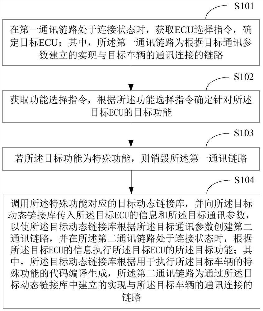
[0065] figure 1 A schematic flow chart of the first vehicle diagnosis method provided by the embodiment of the present application is shown. The vehicle diagnosis method is applied to electronic equipment, and the electronic equipment includes but is not limited to computers and mobile phones installed with a diagnosis client. Such as figure 1 The vehicle diagnostic methods shown are detailed below:
[0066] In S101, when the first communication link is in the connected state, obtain an ECU selection instruction to determine the target ECU; wherein, the first communication link is a link established according to the target communication parameters to realize the communication connection with the target vehicle .
[0067] In the embodiment of the present application, the target vehicle is a vehicle that requires vehicle diagnosis. The first communication link is a communication link established in advance according to target communication parameters in the main program (also...
Embodiment 2
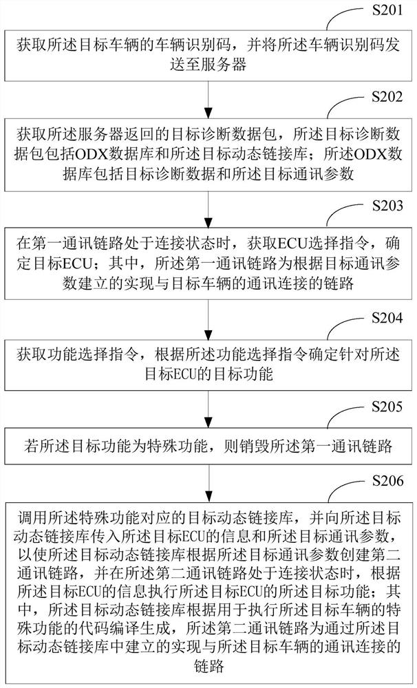
[0087] figure 2 A schematic flow chart of a second vehicle diagnosis method provided by an embodiment of the present application is shown, and the execution body of the vehicle diagnosis method is an electronic device. The vehicle diagnosis method in the embodiment of the present application is further improved on the basis of the method described in the first embodiment, and the same parts as the first embodiment are not repeated here. Such as figure 2 The vehicle diagnostic methods shown are detailed below:
[0088] In S201, acquire a vehicle identification code of the target vehicle, and send the vehicle identification code to a server.
[0089] In the embodiment of the present application, the electronic device automatically sends a vehicle identification number (Vehicle Identification Number, VIN) reading instruction to the target vehicle after receiving the diagnosis startup instruction and starting the client. Afterwards, the vehicle identification code returned by...
Embodiment 3
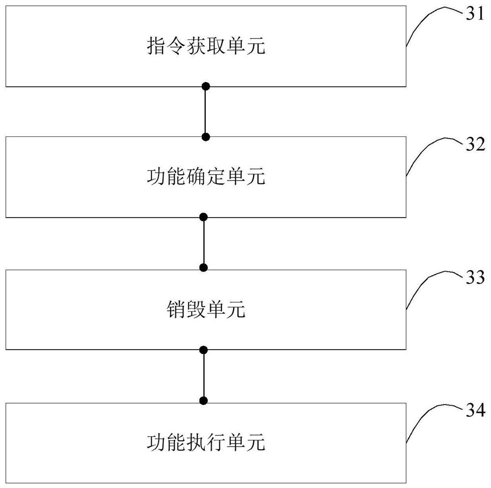
[0146] image 3 A schematic structural diagram of a vehicle diagnostic device provided by the embodiment of the present application is shown. For the convenience of description, only the parts related to the embodiment of the present application are shown:
[0147] The vehicle diagnostic device includes: an instruction acquisition unit 31 , a function determination unit 32 , a destruction unit 33 and a function execution unit 34 .
[0148] Instruction acquiring unit 31, used to acquire the ECU selection instruction and determine the target ECU when the first communication link is in the connected state; wherein, the first communication link is established according to the target communication parameters to realize the communication connection with the target vehicle link.
[0149] The function determining unit 32 is configured to acquire a function selection instruction, and determine a target function for the target ECU according to the function selection instruction.
[01...
PUM
 Abstract
Description
Claims
Application Information
 - R&D
- Intellectual Property
- Life Sciences
- Materials
- Tech Scout
- Unparalleled Data Quality
- Higher Quality Content
- 60% Fewer Hallucinations
Browse by: Latest US Patents, China's latest patents, Technical Efficacy Thesaurus, Application Domain, Technology Topic, Popular Technical Reports.
© 2025 PatSnap. All rights reserved.Legal|Privacy policy|Modern Slavery Act Transparency Statement|Sitemap|About US| Contact US: help@patsnap.com


