Supercharge Your Innovation With Domain-Expert AI Agents!

Method for suppressing overvoltage of sending end of wind, light and water passing through direct current delivery system

An external transmission system, overvoltage technology, applied in the direction of AC network voltage regulation, photovoltaic power generation, AC network circuit, etc., can solve the problem that the excitation system does not play reactive power regulation, etc., to fill the reactive power regulation delay, improve the voltage Distributed, flexible system overvoltage effects

Pending Publication Date: 2022-01-14
NORTH CHINA ELECTRIC POWER UNIV (BAODING)
View PDF4 Cites 0 Cited by
  • Summary
  • Abstract
  • Description
  • Claims
  • Application Information

AI Technical Summary

Problems solved by technology

Therefore, the hydroelectric unit has sufficient reactive power margin, and the excitation system has not exerted its full reactive power adjustment potential

Method used


Image

  • Method for suppressing overvoltage of sending end of wind, light and water passing through direct current delivery system
  • Method for suppressing overvoltage of sending end of wind, light and water passing through direct current delivery system
  • Method for suppressing overvoltage of sending end of wind, light and water passing through direct current delivery system

Examples


Embodiment Construction

[0048] The present invention provides a method for suppressing the overvoltage at the sending end of the wind and water transmission system through a DC external transmission system. In order to make the purpose, technical solution and effect of the present invention clearer, the specific implementation of the present invention will be described in detail below with reference to the accompanying drawings and examples. The specific examples described in the present invention are only used to explain the present invention, not to limit the present invention.

[0049] 1. Introduction to the specific implementation of the invention

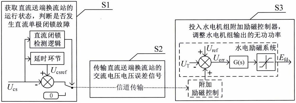
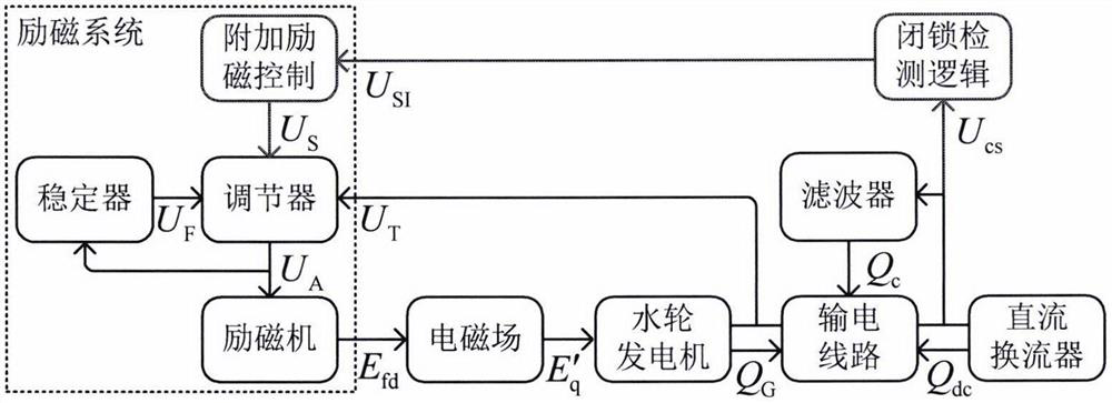
[0050] figure 1 It is a control flow chart of a method for suppressing the overvoltage at the sending end of the wind and water transmission system through the DC external transmission system provided by the present invention, figure 2 The schematic diagram of suppressing the overvoltage of the power system at the sending end of wind and water provi...


PUM


Abstract

The invention discloses a method for suppressing an overvoltage of a sending end of wind, light and water passing through a direct current delivery system. A voltage deviation signal of an alternating-current bus of a direct-current sending-end converter station is used as one of input signals of a hydroelectric generating set excitation system so that the function of suppressing the system overvoltage is achieved. The method comprises the steps that the direct-current operation state is judged according to the voltage, monitored in real time, of the alternating-current bus of the direct-current sending-end converter station; when the direct current blocking detection logic judges that the direct current has a single-pole blocking fault, an alternating current bus voltage error signal of the direct current converter station is transmitted to an additional excitation controller of a specific hydroelectric generating set in a near-region hydropower station through a channel; and the additional excitation controller gains the signal and inputs the signal into an excitation system so that the reactive power output by the hydroelectric generating set is changed. In addition, on the basis of the excitation system output limit and the water motor terminal voltage stability limit, a setting principle of the gain coefficient upper limit of the additional excitation controller is provided. According to the invention, the system overvoltage caused by direct-current single-pole blocking can be effectively suppressed, and the method has economic and practical values.

Description

technical field [0001] The invention relates to the technical field of electric power systems, in particular to a method for suppressing overvoltage at a sending end of a wind and water transmission system via a direct current. Background technique [0002] The western region of my country is rich in wind power, photovoltaic and hydropower resources, which are geographically reversed from the eastern load center. Through the construction of a high-voltage direct current transmission project based on grid commutation converters (hereinafter referred to as direct current), the sending end power grid forms a large-scale wind and water bundling through direct current transmission system, which solves the problem of power energy consumption to a certain extent. [0003] In recent years, with the large-scale grid connection of wind and other new energy sources, the dynamic support capacity of the wind and water delivery system has been declining. If a single-pole blocking fault o...

Claims


Application Information

Patent Timeline
IPC IPC(8): H02J3/38H02J3/36H02J3/16
CPCH02J3/381H02J3/36H02J3/16H02J2300/24H02J2300/28Y02E10/56Y02E40/30Y02E60/60
Inventor 高本锋杨健
Owner NORTH CHINA ELECTRIC POWER UNIV (BAODING)
Features
  • R&D
  • Intellectual Property
  • Life Sciences
  • Materials
  • Tech Scout
  • Unparalleled Data Quality
  • Higher Quality Content
  • 60% Fewer Hallucinations
Learn More