Manufacturing method of shared magnetic core dual-channel wireless electric energy transmission coupling device
A technology of wireless power transmission and coupling device, which is applied in circuit devices, coil manufacturing, inductor/transformer/magnet manufacturing, etc. Coupling and other problems to achieve the effect of ensuring synchronous transmission
- Summary
- Abstract
- Description
- Claims
- Application Information
AI Technical Summary
Problems solved by technology
Method used
Image
Examples
Embodiment 1
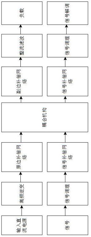
[0038] see figure 1 , a method for manufacturing a shared magnetic core dual-channel wireless power transmission coupling device, comprising the following steps:
[0039] a. Firstly wind the primary signal coil and the primary energy coil on the outer wall of the magnetic ring of the inner cylinder respectively, and the primary energy coil is in contact with the primary signal coil;
[0040] b. Wind the secondary signal coil and the secondary energy coil respectively on the inner wall of the outer cylinder magnetic ring, and the secondary energy coil is in contact with the secondary signal coil;
[0041] c. The outer cylinder magnetic ring is sleeved on the inner cylinder magnetic ring to form an integrated energy transmission channel and signal transmission channel, and a shared magnetic core dual-channel wireless energy transmission coupling device is obtained.
[0042] This embodiment is the most basic implementation mode. a. First, the primary side signal coil and the pri...
Embodiment 2
[0044] see figure 1 , a method for manufacturing a shared magnetic core dual-channel wireless power transmission coupling device, comprising the following steps:
[0045] a. Firstly wind the primary signal coil and the primary energy coil on the outer wall of the magnetic ring of the inner cylinder respectively, and the primary energy coil is in contact with the primary signal coil;
[0046] b. Wind the secondary signal coil and the secondary energy coil respectively on the inner wall of the outer cylinder magnetic ring, and the secondary energy coil is in contact with the secondary signal coil;
[0047]c. The outer cylinder magnetic ring is sleeved on the inner cylinder magnetic ring to form an integrated energy transmission channel and signal transmission channel, and a shared magnetic core dual-channel wireless energy transmission coupling device is obtained.
[0048] It also includes the simulation step, using COMSOL magnetic field simulation software to simulate the mode...
Embodiment 3
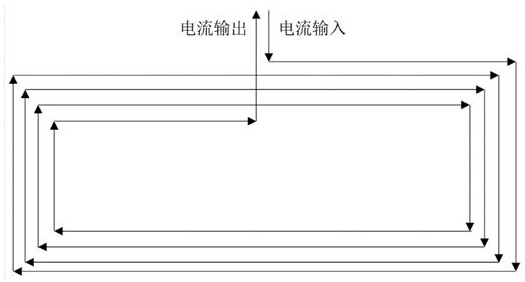
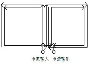
[0051] see Figure 1-Figure 3 , a method for manufacturing a shared magnetic core dual-channel wireless power transmission coupling device, comprising the following steps:
[0052] a. Firstly wind the primary signal coil and the primary energy coil on the outer wall of the magnetic ring of the inner cylinder respectively, and the primary energy coil is in contact with the primary signal coil;
[0053] b. Wind the secondary signal coil and the secondary energy coil respectively on the inner wall of the outer cylinder magnetic ring, and the secondary energy coil is in contact with the secondary signal coil;
[0054] c. The outer cylinder magnetic ring is sleeved on the inner cylinder magnetic ring to form an integrated energy transmission channel and signal transmission channel, and a shared magnetic core dual-channel wireless energy transmission coupling device is obtained.
[0055] It also includes the simulation step, using COMSOL magnetic field simulation software to simula...
PUM
| Property | Measurement | Unit |
|---|---|---|
| thickness | aaaaa | aaaaa |
| height | aaaaa | aaaaa |
Abstract
Description
Claims
Application Information
 - R&D
- Intellectual Property
- Life Sciences
- Materials
- Tech Scout
- Unparalleled Data Quality
- Higher Quality Content
- 60% Fewer Hallucinations
Browse by: Latest US Patents, China's latest patents, Technical Efficacy Thesaurus, Application Domain, Technology Topic, Popular Technical Reports.
© 2025 PatSnap. All rights reserved.Legal|Privacy policy|Modern Slavery Act Transparency Statement|Sitemap|About US| Contact US: help@patsnap.com


