
High-safety new energy vehicle chassis structure

A new energy vehicle, high safety technology, applied in the field of high safety new energy vehicle chassis, can solve the problem of low anti-collision performance, and achieve the effect of improving anti-collision performance and improving safety performance

Inactive Publication Date: 2022-01-18
CHONGQING VOCATIONAL COLLEGE OF TRANSPORTATION
View PDF0 Cites 0 Cited by
  • Summary
  • Abstract
  • Description
  • Claims
  • Application Information

AI Technical Summary

Problems solved by technology

[0004] The present invention intends to provide a high-safety new energy vehicle chassis to solve the problem of low anti-collision performance of the existing new energy vehicle chassis

Method used


Image

  • High-safety new energy vehicle chassis structure
  • High-safety new energy vehicle chassis structure
  • High-safety new energy vehicle chassis structure

Examples


Embodiment 1

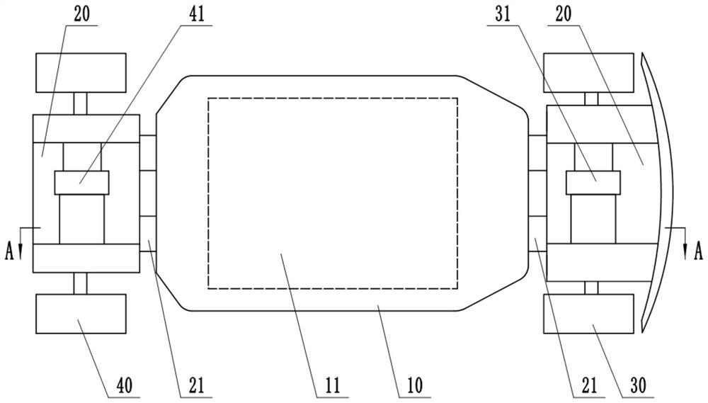
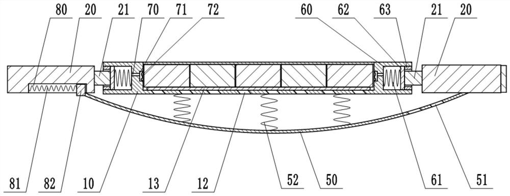
[0023] This embodiment is basically as figure 1 , figure 2 Shown: a high-safety new energy vehicle chassis, including a chassis main board 10, an anti-drag module and installation modules located at the front and rear ends of the chassis main board 10, and a battery installation slot 11 for installing a battery is opened in the chassis main board 10, The chassis main board 10 is provided with a cover plate capable of closing the battery installation slot 11 . Two buffer tanks 60 are opened in the front and rear sides of the chassis main board 10, and the buffer tanks 60 are filled with a buffer fluid, which is hydraulic oil in this embodiment. A piston 62 is slidably and sealed in the buffer tank 60 . The inner wall of the buffer tank 60 is welded with a stopper 63 for preventing the piston 62 from breaking away from the buffer tank 60 . The buffer groove 60 is provided with a first elastic member 61 (the first elastic member 61 in this embodiment is a compressible spring),...

Embodiment 2

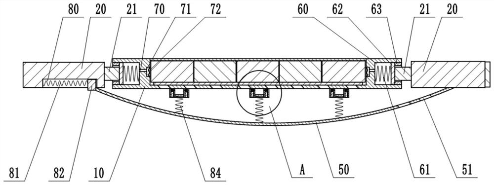
[0028] The difference between this embodiment and Embodiment 1 is that: image 3 , Figure 4 As shown, the structure of the buffer is different. In this embodiment, the buffer includes a third elastic member 91 (the third elastic member 91 in this embodiment is a spring) and a fixing cylinder 90 welded on the chassis main board 10 . The interior of the fixed cylinder 90 is filled with hydraulic oil, and a sliding plug 95 is slid and sealed in the fixed cylinder 90 . The upper end of the third elastic member 91 is connected to the sliding plug 95 , and the lower end of the third elastic member 91 abuts against the elastic steel plate 50 . The side wall of the fixed cylinder 90 is provided with an annular sliding groove 92 facing the side of the elastic steel plate 50, and the inner wall of the fixed cylinder 90 is provided with a channel 93 communicating with the annular sliding groove 92, and the hydraulic oil in the fixed cylinder 90 can pass through the channel 93. into th...


PUM


Abstract

The invention belongs to the technical field of new energy automobiles, and particularly relates to a high-safety new energy vehicle chassis which comprises a chassis main board and mounting modules located at the front end and the rear end of the chassis main board respectively, and a battery mounting groove is formed in the chassis main board; buffer grooves are formed in the front side and the rear side of the chassis main board and filled with buffer liquid. A piston is slidably and hermetically connected in the buffer groove, a connecting column is arranged on the piston, and a first elastic piece is arranged in the buffer groove; the mounting template comprises a supporting frame, and the supporting frame is connected with the connecting column; an annular groove distributed around the battery mounting groove is formed in the chassis main board, the annular groove is communicated with the battery mounting groove, a protective film is arranged on the annular groove, and a closed space is formed between the protective film and the annular groove; and a flow channel is formed between the buffer groove and the annular groove. According to the high-safety new energy vehicle chassis, through the design of the new energy vehicle chassis structure, the chassis has the good anti-collision performance, and the use safety of the chassis is greatly improved.

Description

technical field [0001] The invention belongs to the technical field of new energy vehicles, and in particular relates to a high-safety new energy vehicle chassis. Background technique [0002] New energy vehicles refer to the use of unconventional vehicle fuels as power sources (or the use of conventional vehicle fuels, the use of new vehicle power devices), integrated vehicle power control and advanced technology in driving, the formation of advanced technical principles, with Automobiles with new technology and new structure. Pure electric vehicle is a common new energy vehicle on the market at present. It is a vehicle that mainly uses batteries as the power source for energy storage. Push the car to go. [0003] The car chassis is the skeleton of a pure electric car, and it is an assembly that supports and installs the motor and its components. Most of the existing new energy vehicle chassis are integral, which cannot cushion the force well, and the anti-collision perf...

Claims


Application Information

Patent Timeline
IPC IPC(8): B60K1/04B62D21/15H01M50/244H01M50/249
CPCB60K1/04B62D21/15H01M50/244H01M50/249Y02E60/10
Inventor 鲁守卿
Owner CHONGQING VOCATIONAL COLLEGE OF TRANSPORTATION
Learn More