Silencing steam trap for steam pipe

A sound-absorbing steam trap and steam trap technology, applied in steam traps, pipe components, pipes/pipe joints/fittings, etc., can solve problems such as large noise pollution, loud noise, and human injury, so as to improve safety and reduce noise Pollution and the effect of reducing occupational diseases

Pending Publication Date: 2022-01-18
ANHUI NARADA RENEWABLE RESOURCE TECH CO LTD
View PDF10 Cites 0 Cited by
  • Summary
  • Abstract
  • Description
  • Claims
  • Application Information

AI Technical Summary

Problems solved by technology

[0003] However, the existing steam traps will generate a lot of noise during use, which will cause greater noise pollution in the factory area, and the ears of the staff who have worked here for a long time will be injured to varying degrees, thereby causing harm to the human body and increasing the risk of occupational diseases. At the same time, most of the condensed water in the existing steam traps is directly discharged or flows to the ground to be evaporated, resulting in a waste of resources

Method used


Image

  • Silencing steam trap for steam pipe
  • Silencing steam trap for steam pipe
  • Silencing steam trap for steam pipe

Examples


Embodiment 1

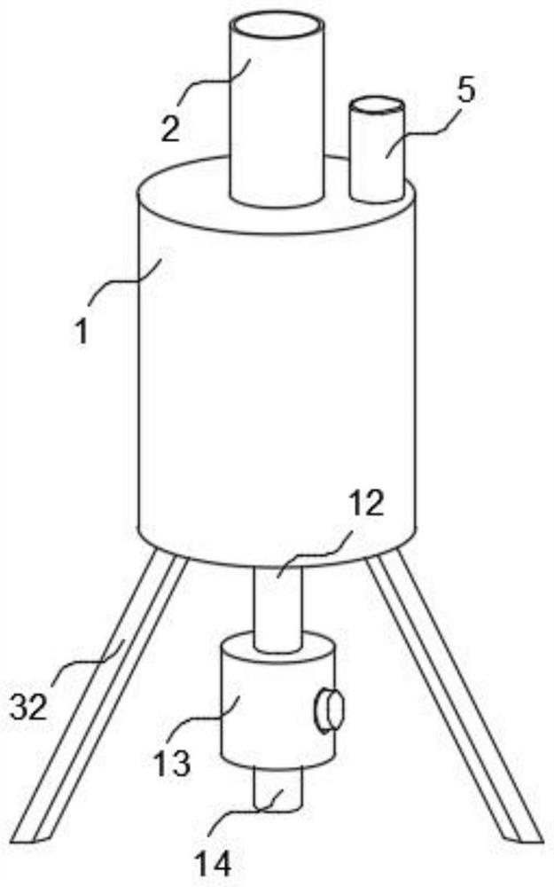
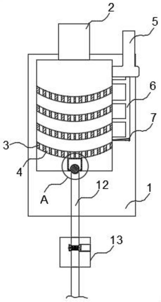
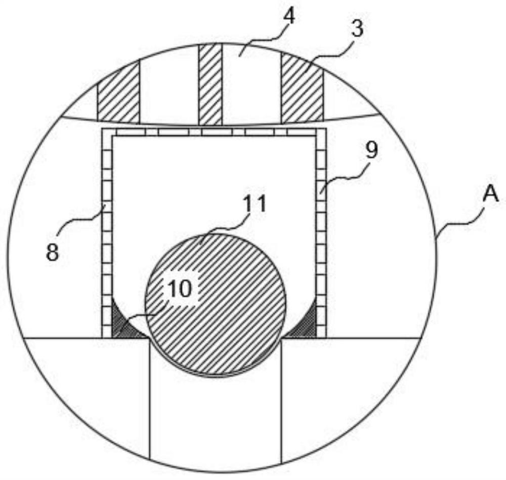
[0029] Such as Figure 1-8 As shown, the present invention proposes a sound-absorbing steam trap for steam pipes, including a steam trap main body 1, an air inlet pipe 2 is provided on the outer surface of the upper end of the steam trap main body 1 near the middle position, and the interior of the steam trap main body 1 is equidistant from There are several fixed plates 3 fixedly connected, and the fixed plates 3 are in an arc-shaped structure, which are used to guide the water generated by the gas, and can introduce water into the bottom of the steam trap main body 1 for collection. The outer surfaces of the upper ends of the fixed plates 3 are equidistant from each other. Several through holes 4 are provided, and an exhaust pipe 5 is provided on one side of the main body of the steam trap near the upper end. The air hole is used to guide the gas into the exhaust pipe 5 for discharge, and it communicates with the inside of the steam trap main body 1. The inside of the air gu...

Embodiment 2

[0033] Such as Figure 1-8 As shown, the first drain pipe 12 penetrates to the inside of the steam trap main body 1 and extends to the outside. The outer surface of the lower end of the first drain pipe 12 is fixedly connected with an attachment 13, and the interior of the attachment 13 A second drainpipe 14 is provided near the middle position, and the second drainpipe 14 and the first drainpipe 12 communicate with each other. The right side outer surface of the add-on part 13 is provided with a mounting groove 15 near the middle position, and the installation The groove 15 communicates with the second drain pipe 14. A rotating block 16 is arranged inside the installation groove 15 for fixing the fixed block 19. The left outer surface of the rotating block 16 is fixedly connected with a connector 17. The outer surface of the left side of the connector 17 is provided with a fixed block 19, and the inner middle position of the fixed block 19 is provided with a threaded groove 2...


PUM


Abstract

The invention relates to a silencing steam trap for a steam pipe. The silencing steam trap comprises a steam trap main body, wherein an air inlet pipe is arranged at the position, close to the middle, of the outer surface of the upper end of the steam trap main body, a plurality of fixing plates are fixedly connected to the interior of the steam trap main body at equal intervals, the fixing plates are of an arc-shaped structure, a plurality of through holes are formed in the outer surfaces of the upper ends of the fixing plates at equal intervals, an exhaust pipe is arranged at the position, close to the upper end, of one side of the interior of the steam trap main body, an air guide pipe is arranged at the lower end of the exhaust pipe, a plurality of exhaust holes are formed in the air guide pipe, the air guide pipe communicates with the interior of the steam trap main body, and a guide plate is fixedly connected to the position, located at the lower end, of the interior of the air guide pipe. According to the silencing steam trap, the noise of a factory area can be reduced, the noise pollution of the factory area is reduced, the safety of workers is improved, the induction of occupational diseases is reduced, meanwhile, discharged water can be effectively filtered, the quality of later water is improved, the quality of the water is improved for later water recovery, and the waste of resources is reduced.

Description

technical field [0001] The invention relates to the field of steam traps, in particular to a sound-absorbing steam trap for steam pipes. Background technique [0002] Steam traps are called steam traps, also called automatic drains or condensate drains, which are used in steam systems and gas systems. Thermostatic steam traps use different temperatures of steam and water to cause temperature-sensitive components to act. To achieve the purpose of controlling the valve. [0003] However, the existing steam traps will generate a lot of noise during use, which will cause greater noise pollution in the factory area, and the ears of the staff who have worked here for a long time will be injured to varying degrees, thereby causing harm to the human body and increasing the risk of occupational diseases. At the same time, most of the condensed water in the existing steam traps is directly discharged or flows to the ground to be evaporated, thus causing a waste of resources. [0004...

Claims


Application Information

Patent Timeline
Patent Type & Authority Applications(China)
IPC IPC(8): F16T1/00F16T1/20F16T1/38F16L55/033
CPCF16T1/00F16T1/20F16T1/38F16L55/033
Inventor 曲文中周红飞
Owner ANHUI NARADA RENEWABLE RESOURCE TECH CO LTD
Why Eureka
Try Eureka