
Optical imaging display system and near-eye display equipment

An optical display, optical imaging technology, applied in optics, optical components, instruments, etc., can solve the problems of poor image quality, inconsistent size, large volume, etc., and achieve the effect of improving user experience and quality

Inactive Publication Date: 2022-01-18
JOURNEY TECH LTD +1
View PDF6 Cites 0 Cited by
  • Summary
  • Abstract
  • Description
  • Claims
  • Application Information

AI Technical Summary

Problems solved by technology

However, due to the relatively large volume of the image acquisition and processing module and the optical display module, the volume and weight of the AR device will increase
Moreover, since the image acquisition and processing module and the optical display module are set separately and each uses its own independent optical system, the field angles of the optical systems of the two modules may be inconsistent, which may cause the image acquisition and processing module and the optical display The problem of inconsistency in the field of view of the module leads to inconsistency in size when the virtual image and the real image are superimposed, resulting in poor image quality displayed by the AR device and reducing user experience

Method used


Image

  • Optical imaging display system and near-eye display equipment
  • Optical imaging display system and near-eye display equipment
  • Optical imaging display system and near-eye display equipment

Examples


Embodiment Construction

[0034] The technical solution in this application will be described below with reference to the accompanying drawings.

[0035] In the description of the embodiments of this application, unless otherwise specified, " / " means or means, for example, A / B can mean A or B; "and / or" in this article is only a description of the association of associated objects A relationship means that there may be three kinds of relationships, for example, A and / or B means: A exists alone, A and B exist simultaneously, and B exists independently. In addition, in the description of the embodiments of the present application, "plurality" refers to two or more than two.

[0036] Hereinafter, the terms "first" and "second" are used for descriptive purposes only, and cannot be understood as indicating or implying relative importance or implicitly specifying the quantity of indicated technical features. Thus, a feature defined as "first" and "second" may explicitly or implicitly include one or more of t...


PUM


Abstract

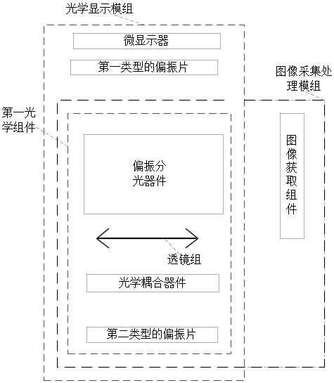
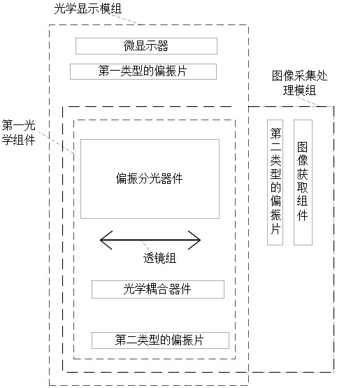
The invention provides an optical imaging display system and near-to-eye display equipment. The optical imaging display system can be applied to the near-to-eye display equipment. The optical imaging display system comprises an image acquisition and processing module and an optical display module, wherein the image acquisition and processing module comprises an image acquisition assembly and a first optical assembly; the optical display module comprises a micro-display and a first optical assembly. The first optical assembly comprises a polarizing beam splitter, a lens group, an optical coupling device and a polarizer of a second type. The image acquisition and processing module and the optical display module share the first optical assembly, so that the problem that the near-to-eye display equipment is large in size and weight due to the fact that the image acquisition and processing module and the optical display module are independently arranged is solved; moreover, the field angle of the image acquisition and processing module is consistent with that of the optical display module, so that the problem of size inconsistency when the virtual image and the real image of the near-to-eye display equipment are superposed is solved, and the quality of the image displayed to the user is improved.

Description

technical field [0001] The present application relates to the field of virtual reality display, and more specifically, to an optical imaging display system and a near-eye display device. Background technique [0002] Augmented reality (augmented reality, AR) and virtual reality (virtual reality, VR) technologies use near-eye display solutions to superimpose virtual images on real scenes and provide users with immersive and interactive experiences, which have become research hotspots in recent years. one. [0003] At present, AR equipment generally includes an image acquisition and processing module and an optical display module, and the two modules are set separately. Among them, the image acquisition and processing module mainly includes image acquisition components (including lenses and photoelectric sensors, etc.) and some optical devices. Used to collect image information of the real world. The optical display module mainly includes a microdisplay and some optical devi...

Claims


Application Information

Patent Timeline
Patent Type & Authority Applications(China)
IPC IPC(8): G02B27/01
CPCG02B27/0172
Inventor 雍海波郑昱赵鑫
Owner JOURNEY TECH LTD
Learn More