A hydraulic jet oscillator element

A technology of hydraulic jet and oscillator, applied in the direction of spraying device, liquid spraying device, etc., to achieve the effects of increased oscillation amplitude, easy frequency control, and convenient installation

Active Publication Date: 2022-07-29
CENT SOUTH UNIV
View PDF5 Cites 0 Cited by
  • Summary
  • Abstract
  • Description
  • Claims
  • Application Information

AI Technical Summary

Problems solved by technology

[0005] The invention provides a hydraulic jet oscillator element, the purpose of which is to solve the problem of relying on the feedback channel in the prior art to achieve oscillation

Method used


Image

  • A hydraulic jet oscillator element
  • A hydraulic jet oscillator element
  • A hydraulic jet oscillator element

Examples


Embodiment Construction

[0025] In order to make the technical problems, technical solutions and advantages to be solved by the present invention clearer, detailed description will be given below with reference to the accompanying drawings and specific embodiments.

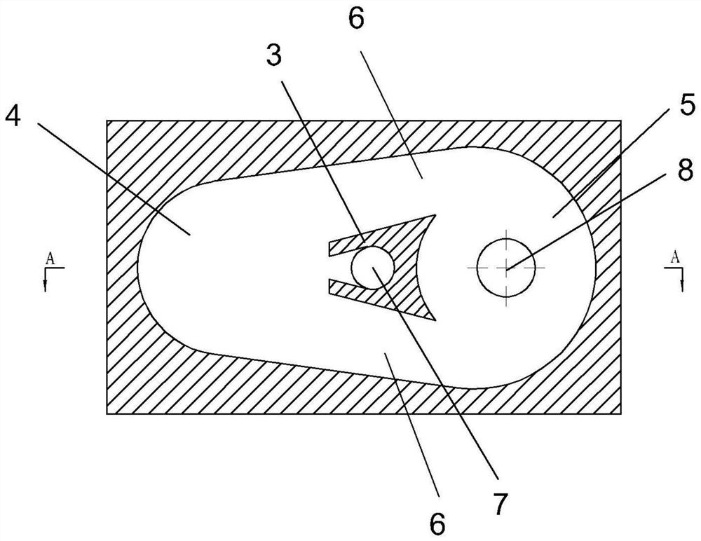
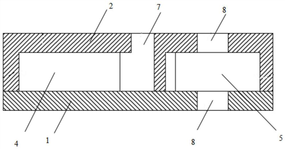
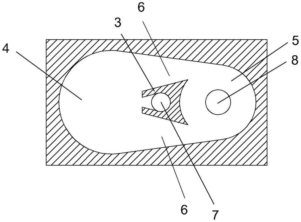
[0026] like figure 1 and 2 As shown, the embodiment of the present invention provides a hydraulic jet oscillator element, which includes a cover plate 1, a base plate 2 and a side wall, the base plate 2, the cover plate 1 and the side wall form a cavity, and a cavity is also provided in the cavity The jet member 3 divides the cavity into an oscillating cavity 4 , a vortex cavity 5 and an output channel 6 , wherein the output channel 6 is formed by the jet member 3 and the side wall, and its function is to communicate the oscillating cavity 4 and the vortex cavity 5 .

[0027] The jet member 3 includes a semi-closed groove for fluid flow, the opening direction of the semi-closed groove is toward the oscillating cavity 4, and the vortex ca...


PUM


Abstract

The invention provides a hydraulic jet oscillator element, which relates to the field of oscillators and includes a cover plate, a base plate and a side wall. The cover plate, the base plate and the side wall form a cavity, and a jet member is arranged in the cavity and separates the cavity into oscillations. The cavity, the vortex cavity and the output channel, the oscillating cavity and the vortex cavity are communicated through the output channel, the jet member is provided with a semi-closed groove for fluid flow, the oscillating cavity is facing the opening direction of the semi-closed groove, and the vortex cavity is facing away from the opening of the semi-closed groove The inflow hole is arranged on the cover plate, and the inflow hole communicates with the semi-closed groove; the first outflow hole is arranged on the cover plate and / or the base plate, and the first outflow hole communicates with the vortex cavity. The mechanism, only relying on the internal fluid channel setting, can self-excite to generate periodic fluid oscillation; without any movable parts, it is easy to manufacture and durable; compared with other types of fluidic oscillators, the oscillation amplitude is increased, and the frequency is easy to regulation.

Description

technical field [0001] The invention relates to the field of oscillators, in particular to a hydraulic jet oscillator element. Background technique [0002] A fluidic oscillator is a device that does not require mechanical moving parts, but only generates a continuously oscillating jet through fluid interaction. It has excellent scalability and integratability, a large bandwidth from a few Hz to tens of thousands of Hz, robustness to operate in harsh environments, and its inherent oscillatory characteristics. In recent decades, jet oscillators have achieved widespread success in issues such as flow control, separation control, downhole cleaning, downhole oscillation, and jet impingement. [0003] The existing jet oscillation device mainly adopts the principle of Coanda. Based on the Coanda effect, when a certain pressure of fluid enters the mixing chamber of the jet vibrator from the inlet, the main flow will selectively adhere to one side of the wall, so as to follow the w...

Claims


Application Information

Patent Timeline
Patent Type & Authority Patents(China)
IPC IPC(8): B05B17/04
CPCB05B17/04
Inventor 张鑫鑫毛纯芝吴章辉唐禄博马立科陆霄罗紫琪李若曦张常溢
Owner CENT SOUTH UNIV
Why Eureka
Try Eureka