Vertical flanging machine

A flanging machine, vertical technology, applied in the direction of forming tools, safety equipment, applications, etc., can solve the problems of increasing the size of the cup shell, low efficiency of the horizontal flanging machine, non-parallel inner tank and shell, etc. Easy to guarantee, the upper mold device has a simple structure, and the effect of saving materials

Active Publication Date: 2022-01-21
ZHEJIANG HAERS VACUUM CONTAINERS CO LTD
View PDF44 Cites 0 Cited by
  • Summary
  • Abstract
  • Description
  • Claims
  • Application Information

AI Technical Summary

Problems solved by technology

The efficiency of the horizontal flanging machine is low, and the verticality between the flanging and the cup body is poor, which leads to the non-parallel between the inner tank and the outer shell after welding, the gap is uneven, and even the wall is bumped, resulting in defective products.
Based on the above defects, in order to avoid the occurrence of defective products caused by bumping into the wall, the only way to increase the size of the cup shell is at present
This not only wastes material, but also increases the size of the product

Method used


Image

  • Vertical flanging machine
  • Vertical flanging machine
  • Vertical flanging machine

Examples


Embodiment Construction

[0030] In order to make the technical solution of the present invention clearer, the following in conjunction with the attached Figures 1 to 12 , the present invention will be described in detail. It should be understood that the specific implementations described in this specification are only for explaining the present invention, and are not intended to limit the protection scope of the present invention.

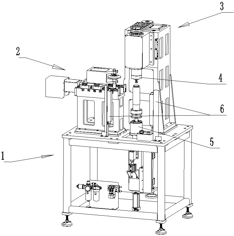
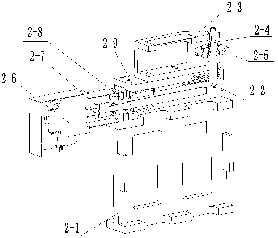
[0031]The present invention is a vertical flanging machine, comprising a base 1, a pressing wheel device 2, a column device 3, an upper die device 4 and a lower die device 5; And the pinch wheel 2-5 that can rotate around the pinch wheel shaft 2-4 axis is used for the flanging of the port of the liner, and the pinch wheel shaft 2-4 is vertically arranged on a drive source (preferred servo motor 2-6) that can On the pressure wheel frame 2-3 that moves horizontally along the line rail 2-2, the line rail 2-2 is arranged on the top of the machine base 2-1, and the machine b...


PUM


Abstract

The invention discloses a vertical flanging machine. The vertical flanging machine comprises a base, a pressing wheel device, a stand column device, an upper mold device and a lower mold device, wherein the stand column device comprises a main shaft; the upper mold device is detachably arranged at the lower end of the main shaft; a main shaft driving mechanism drives the main shaft to rotate, so as to drive the upper mold device to rotate; the upper mold device comprises an upper mold detachably arranged at the lower end of the main shaft, a flanging sleeve and a double-taper sleeve are arranged below the upper mold, and the upper end part of a guide rod sleeved with an upper mold reset spring penetrates through a middle hole of the double-taper sleeve to be in threaded connection with the middle of the lower end of the upper mold; and the lower mold device comprises a lower mold assembly, the lower mold assembly comprises a lower mold and a lower mold shaft, and the lower end of the lower mold shaft is connected with a driving mechanism to complete mold assembly or separation of the lower mold shaft and the upper mold device. According to the vertical flanging machine, the flanging perpendicularity of an inner container is better, the production efficiency is higher, and the rejection rate is lower, so that the outer diameter of a housing corresponding to the vertical flanging machine can be reduced, the materials are saved, the cost is reduced, and a vacuum cup is smaller and more exquisite on the premise of the same capacity.

Description

technical field [0001] The invention relates to processing equipment for thermos cups, in particular to a vertical flanging machine. Background technique [0002] In order to prevent the mouth of the metal thermos cup from scratching the user, the liner of the thermos cup needs to be flanged outwards, and then the outer shell of the liner needs to be fitted. [0003] For conventional thermos cups that adopt the welding process of arc mouth after flanging, since the outer diameter of the flanging of the mouth of the liner is larger than the inner diameter of the mouth of the outer shell after the mouth is rotated, the inner liner cannot be inserted into the outer shell for matching welding, so the inner liner needs to be welded first After the liner is put into the shell, the mouth of the inner liner is flanged, and finally the mouth is welded. For the above process, the currently widely used flanging machine is a horizontal flanging machine, such as "a stainless steel cup c...

Claims


Application Information

Patent Timeline
Patent Type & Authority Applications(China)
IPC IPC(8): B21D19/04B21D51/18B21D37/10B21D37/12B21D55/00
CPCB21D19/046B21D51/18B21D37/10B21D37/12B21D55/00Y02P70/10
Inventor 朱毅余诺杜金生
Owner ZHEJIANG HAERS VACUUM CONTAINERS CO LTD
Why Eureka
Try Eureka