Main platform splicing and constructing pneumatic tool assembly

A technology of pneumatic tooling and main platform, applied in the field of machining, can solve the problems of difficulty in ensuring the verticality of the side plate and the bottom plate, difficult welding quality, large weight and volume, etc. The effect of reducing labor intensity

Inactive Publication Date: 2013-08-28
柳州市柳吉汽车配件厂
View PDF3 Cites 0 Cited by
  • Summary
  • Abstract
  • Description
  • Claims
  • Application Information

AI Technical Summary

Problems solved by technology

[0002] The main platform is an important component of the excavator. The engine and other components of the excavator are set on the main platform. The main platform is mainly composed of the bottom plate A, side plate B and connecting Plates C and D are formed by welding, see Figure 7 As shown in Figure 8, bottom plate A, side plate B and The connecting plates C and D are relatively large steel parts with large weight and volume. Generally, the side plate B and the connecting plates C and D are manually clamped with various positioning plates to make the side plate B and the connecting plate C , D and the position of the bottom plate A are relatively fixed, the side plate B and the connecting plates C and D are positioned on the bottom plate A by spot welding, and then the side plate B and the connecting plates C and D are respectively connected to the bottom plate A through systematic welding. Welded together, since the side plate B and the bottom plate A need to be kept vertical, the side plate must be positioned well during clamping. Using the above clamping method, it takes a long time to complete the clamping of a set of main platform, and the work efficiency is low. Since the positioning plates are not strictly symmetrically arranged, the force exerted on the side plates by manual clamping of each positioning plate can not help but be the same, it is difficult to ensure the verticality of the side plate and the bottom plate, so it is not easy to ensure the welding quality
In addition, the labor intensity of manual clamping workers is relatively high

Method used


Image

  • Main platform splicing and constructing pneumatic tool assembly
  • Main platform splicing and constructing pneumatic tool assembly
  • Main platform splicing and constructing pneumatic tool assembly

Examples


Embodiment Construction

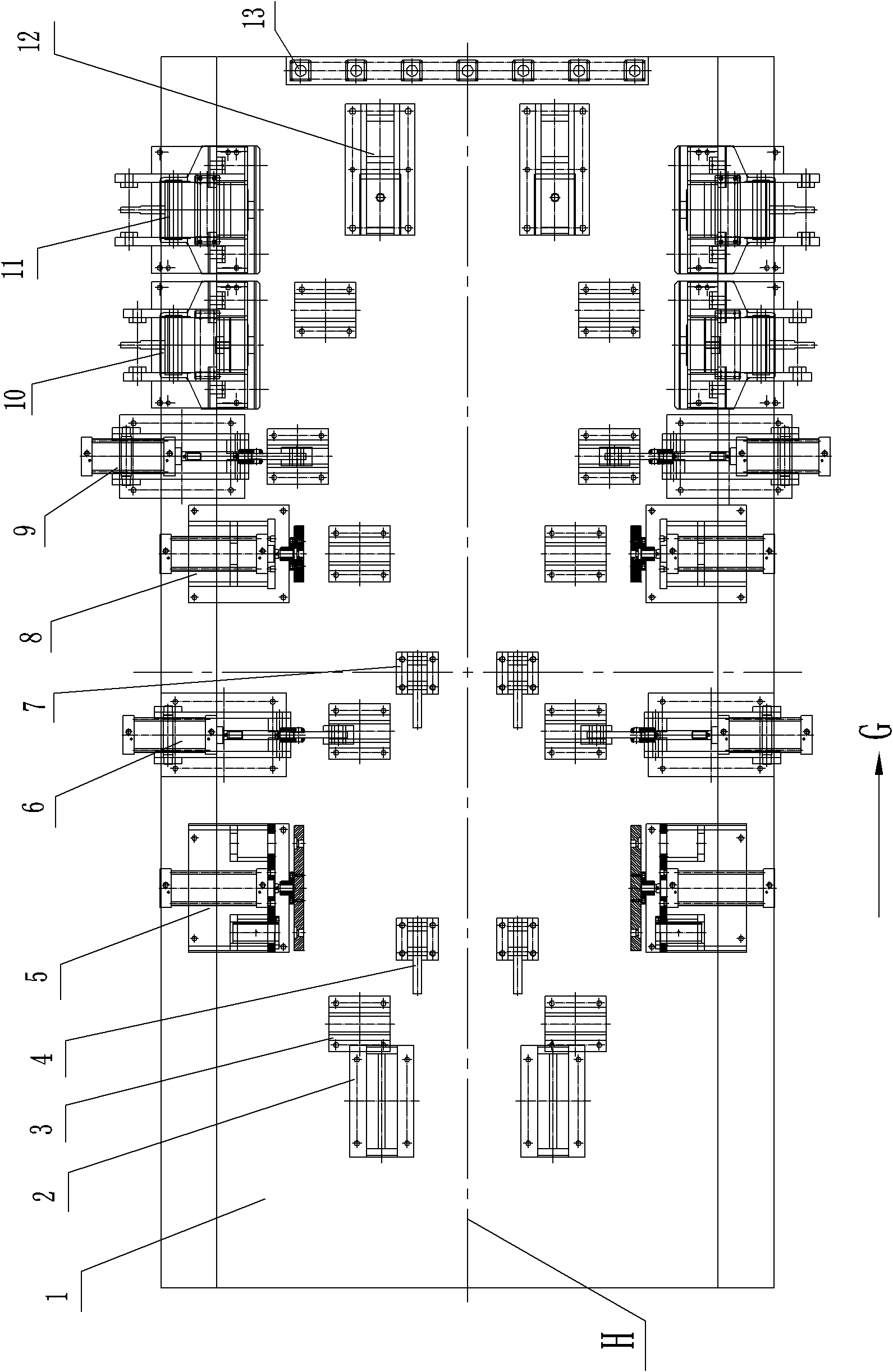
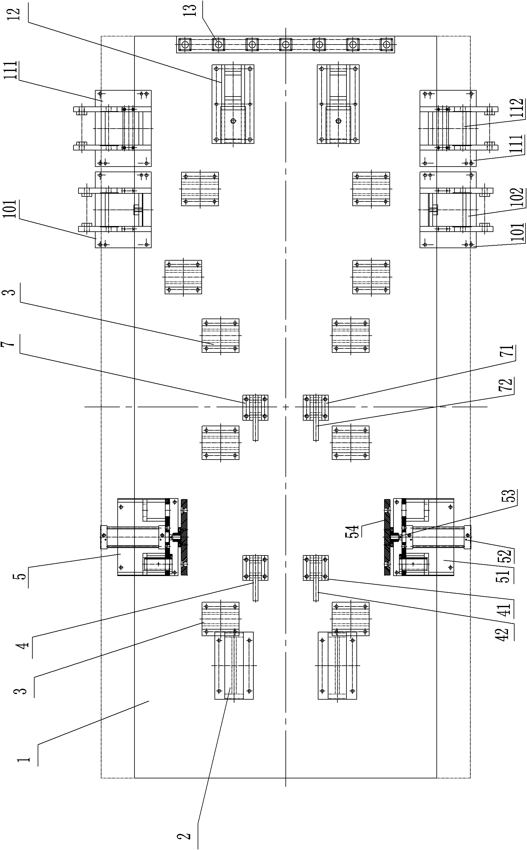
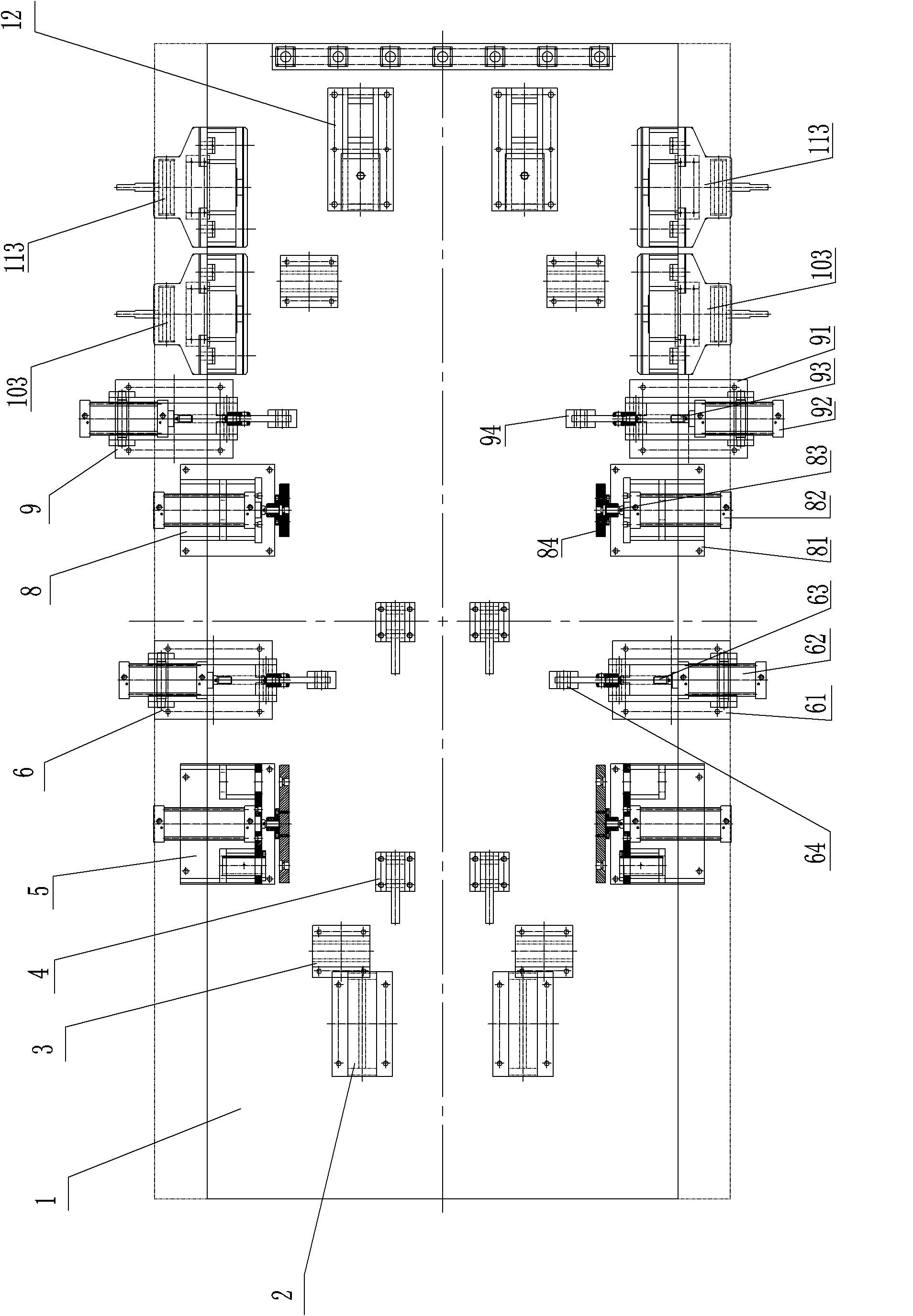
[0033] Such as Figure 1 to Figure 11 As shown, the main platform of the present invention builds a pneumatic tooling assembly. The pneumatic tooling includes a base 1 and a base plate seat 3 fixedly connected to the base 1, a counterweight support seat 2, a rear positioning seat 5, and a rear floor press. Seat 6, middle side positioning seat 8, front floor pressing seat 9, oil cylinder positioning seat 10 on the side plate, oil cylinder positioning seat 11 under the side plate, rear connecting plate positioning seat 4 and middle connecting plate positioning seat 7. figure 1 The direction indicated by the middle arrow G is the forward direction, and the direction opposite to the arrow G is the backward direction.

[0034] Base plate pedestals 3 are symmetrically arranged on both sides of base 1. Base plate pedestals 3 are used to support the main platform base plate A to ensure the flatness of the main platform base plate A. Since the base 1 is large, it is difficult to ensur...


PUM


Abstract

The main platform assembly pneumatic tooling assembly of the present invention relates to a tooling used in the field of mechanical processing. The pneumatic tooling includes a base, a base plate seat fixedly connected to the base, a counterweight support seat, a rear positioning seat, and a rear floor. The pressing seat, the middle side positioning seat, the front floor pressing seat, the oil cylinder positioning seat on the side plate, the oil cylinder positioning seat under the side plate, the positioning seat of the rear connecting plate and the positioning seat of the middle connecting plate, and the bottom plate seat are symmetrically arranged on the base The upper and rear positioning seats, the rear floor pressing seat, the middle side positioning seat, the front floor pressing seat, the oil cylinder positioning seat on the side plate, and the oil cylinder positioning seat under the side plate are symmetrically arranged on both sides of the base, and the rear connection The plate positioning seat and the middle connecting plate positioning seat, the rear connecting plate positioning seat and the middle connecting plate positioning seat are respectively arranged in the middle of the base rear end and the middle end position.

Description

technical field [0001] The invention relates to a tooling used in the field of mechanical processing, in particular to a pneumatic tooling used in assembly. Background technique [0002] The main platform is an important component of the excavator. The engine and other components of the excavator are set on the main platform. The main platform is mainly formed by welding the bottom plate A, side plate B and connecting plates C and D. See Figure 7 Figure 8 As shown, the bottom plate A, the side plate B and the connecting plates C and D are all relatively large steel parts with large weight and volume. Generally, the side plate B and the connecting plates C and C are manually clamped with various positioning plates. D, After fixing the positions of side plate B, connecting plate C, D and bottom plate A relatively, position side plate B, connecting plate C, D on the bottom plate A by spot welding, and then make side plate B through systematic welding And the connecting plat...

Claims


Application Information

Patent Timeline
Patent Type & Authority Patents(China)
IPC IPC(8): B23P21/00B23K37/04
Inventor 洪超
Owner 柳州市柳吉汽车配件厂
Why Eureka
Try Eureka