
Cutting sawing machine for short bar machining

A technology for cutting saws and short bars, which is applied in sawing machine devices, metal processing equipment, attachment devices of sawing machines, etc., can solve the problem of inability to process and cut short bars, and achieves improved applicability and functionality, improved stability, and improved The effect of practicality

Pending Publication Date: 2022-01-21
临沂市鲁蒙水表制造有限公司
View PDF0 Cites 2 Cited by
  • Summary
  • Abstract
  • Description
  • Claims
  • Application Information

AI Technical Summary

Problems solved by technology

[0004] The object of the present invention is to provide a cutting saw machine for short bar processing, aiming to solve the problem in the prior art that short bar processing and cutting cannot be performed on ordinary sawing machines

Method used


Image

  • Cutting sawing machine for short bar machining
  • Cutting sawing machine for short bar machining
  • Cutting sawing machine for short bar machining

Examples


Embodiment 1

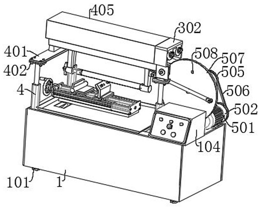
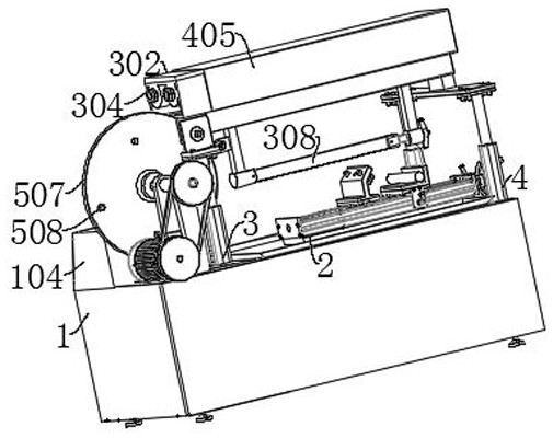
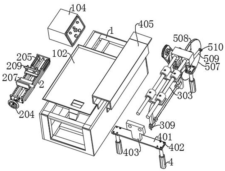
[0038] see Figure 1-Figure 9 , the present invention provides the following technical solutions:

[0039] A cut-off sawing machine for processing short bars, comprising:

[0040] base1;

[0041] The chip containing liquid pan 102, the chip containing liquid pan 102 is fixedly connected to the upper end of the base 1, the upper end of the chip containing liquid pan 102 is fixedly connected with the first fixed platform 2, and the upper end of the first fixed platform 2 is fixedly connected with the sliding platform 201; and

[0042]Rotation mechanism: The rotation mechanism includes a fixed frame 5, a rotating shaft 504, a disc 507, a mounting groove 508, a connecting rod 509 and a third bolt 510, the fixed frame 5 is fixedly connected to the upper end of the base 1, and the rotating shaft 504 is rotatably connected to the fixed frame 5 The side end, the disc 507 is fixedly connected to the side end of the rotating shaft 504, the installation groove 508 is opened on the side...


PUM


Abstract

The invention provides a cutting sawing machine for short bar machining and belongs to the technical field of cutting. The cutting sawing machine for the short bar machining comprises a base, a chip liquid containing disc and a rotating mechanism, wherein the chip liquid containing disc is fixedly connected to the upper end of the base, a first fixing table is fixedly connected to the upper end of the chip liquid containing disc, and a sliding table is fixedly connected to the upper end of the first fixing table; and the rotating mechanism comprises a fixing frame, a rotating shaft, a disc, a mounting groove, a connecting rod and a third bolt, the fixing frame is fixedly connected to the upper end of the base, the rotating shaft is rotatably connected to the side end of the fixing frame, the disc is fixedly connected to the side end of the rotating shaft, the mounting groove is formed in the side end of the disc, the connecting rod is connected to the side end of the disc, and the third bolt is connected in the mounting groove in a threaded manner. According to the cutting sawing machine for the short bar machining, a self-made and cast lathe bed is used as the base, the precise hard rail sliding table is added, a reasonable clamp and a reliable saw blade clamping part are further arranged, the length can be adjusted freely and conveniently, use is easy to operate, and potential safety hazards do not exist.

Description

technical field [0001] The invention belongs to the technical field of cutting, and in particular relates to a cutting saw machine for processing short bars. Background technique [0002] The servo position control module of the sawing machine system adopts the position control combining sampling interpolation and predictive control (the specific control is omitted). Shanghai Guangnai Electromechanical determines the position to close the feeding cylinder through the system experience value and current state, so that the feeding cylinder just reaches the target when it stops Location. Due to the electromagnetic mechanical hysteresis and motion inertia, it is almost impossible to control the movement of the feeding slide by 0.1mm by "on" and "off". In order to ensure the minimum feeding length and feeding accuracy, the rear clamp makes the feeding slide back to the LK position, and then moves forward to the predicted position LT to close the feeding solenoid valve. The rear...

Claims


Application Information

Patent Timeline
Patent Type & Authority Applications(China)
IPC IPC(8): B23D45/00B23D59/00B23Q11/00
CPCB23D45/00B23D59/00B23Q11/00
Inventor 赵清田张永志姜春亮刘常斌
Owner 临沂市鲁蒙水表制造有限公司
Learn More