
Part splicing equipment with conveying structure for machining

A technology for mechanical processing and parts, which is applied in the field of parts splicing equipment with conveying structure for mechanical processing, can solve the problems of affecting splicing quality, prone to deviation in splicing process, and not having automatic conveying structure, etc., so as to achieve easy connection, Guarantee the effect of continuity, effectiveness and accuracy

Inactive Publication Date: 2022-01-21
重庆信易源智能科技有限公司
View PDF0 Cites 2 Cited by
  • Summary
  • Abstract
  • Description
  • Claims
  • Application Information

AI Technical Summary

Problems solved by technology

[0004] The object of the present invention is to provide a part splicing device with a conveying structure for mechanical processing, so as to solve the problem that the mechanical processing part splicing device proposed in the above background technology does not have an automatic conveying structure, and requires staff to manually load materials. There is a certain safety risk, and at the same time, it is easy to shift during the splicing process, which affects the quality of splicing

Method used


Image

  • Part splicing equipment with conveying structure for machining
  • Part splicing equipment with conveying structure for machining
  • Part splicing equipment with conveying structure for machining

Examples


Embodiment Construction

[0026] The technical solutions in the embodiments of the present invention will be clearly and completely described below in conjunction with the accompanying drawings in the embodiments of the present invention. Obviously, the described embodiments are only some of the embodiments of the present invention, not all of them. Based on The embodiments of the present invention and all other embodiments obtained by persons of ordinary skill in the art without making creative efforts belong to the protection scope of the present invention.

[0027] In the description of the present invention, unless otherwise stated, the meaning of "plurality" is two or more; the terms "upper", "lower", "left", "right", "inner", "outer" , "front end", "rear end", "head", "tail", etc. indicate the orientation or positional relationship based on the orientation or positional relationship shown in the drawings, and are only for the convenience of describing the present invention and simplifying the desc...


PUM


Abstract

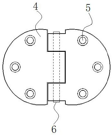
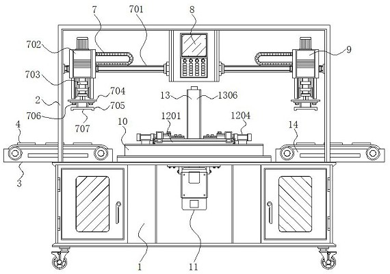
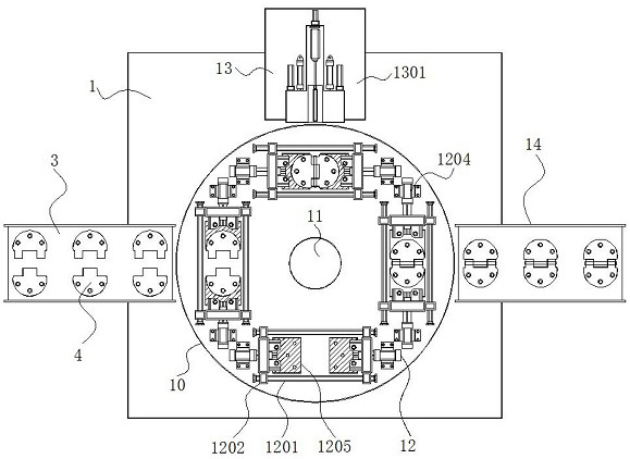
The invention discloses part splicing equipment with a conveying structure for machining, and relates to the technical field of machining. The part splicing equipment comprises a base, a clamping mechanism and a splicing mechanism, a placement frame is arranged at the position, close to the edge, of the upper end of the base, a feeding conveying belt is arranged on the left side of the upper end of the base, by means of a magnetic suction plate and a connecting block which are distributed in parallel, the position accuracy between the magnetic suction plate and the connecting block can be guaranteed, the magnetic suction plate connected with the connecting block through a fastening bolt is convenient to mount, dismount and replace, a hinge body can be well protected by means of a protection layer arranged on the upper surface of the magnetic suction plate in a matched mode, the situation that scratches appear on the surface of the hinge body in the splicing process is avoided, limiting columns arranged at the upper end of the magnetic suction plate are matched with threaded holes formed in the two sides of the hinge body, the accuracy of the hinge body placed at the upper end of the magnetic suction plate each time can be guaranteed, the hinge body can be subjected to power-on adsorption and power-off loosening through the magnetic suction plate, and the splicing efficiency is effectively improved.

Description

technical field [0001] The invention relates to the technical field of mechanical processing, in particular to a parts splicing device with a conveying structure for mechanical processing. Background technique [0002] Machining refers to the process of changing the shape or performance of the workpiece through a mechanical device. According to the difference in processing methods, it can be divided into cutting processing and pressure processing. Hinge processing is a kind of mechanical processing. In the process of hinge processing Part splicing equipment is required. [0003] The splicing equipment for machined parts on the market does not have an automatic conveying structure, and the staff needs to manually load the material. There are certain safety risks in the feeding process. At the same time, deviations are prone to occur during the splicing process, which affects the splicing quality. Contents of the invention [0004] The object of the present invention is to ...

Claims


Application Information

Patent Timeline
Patent Type & Authority Applications(China)
IPC IPC(8): B23P19/00B23P19/04B65G47/04B65G47/92
CPCB23P19/001B23P19/002B23P19/006B23P19/04B65G47/04B65G47/92
Inventor 谢晶晶梁志淙邝海桥
Owner 重庆信易源智能科技有限公司
Learn More