Automatic control device for industrial robot

An automatic control and industrial robot technology, which is applied in the direction of manipulators, manufacturing tools, chucks, etc., can solve the problems of easy wear, rough outer peripheral surface of the driving column, and unsmooth sliding of the driving column, and achieve better results.

Inactive Publication Date: 2022-01-21
李进华
View PDF0 Cites 0 Cited by
  • Summary
  • Abstract
  • Description
  • Claims
  • Application Information

AI Technical Summary

Problems solved by technology

[0004] After the data parameters are manipulated, the robotic automation control device can complete the actions of grasping, transposition, and placement of objects by itself. To complete these actions smoothly, it is necessary to ensure that the driving column can slide stably in the displacement rail, which is cylindrical and copper-plated. The driving column made of iron is prone to wear and rust during sliding, which makes the outer peripheral surface of the driving column not smooth, resulting in the unsmooth sliding of the driving column in the displacement rail, which affects the automatic operation of the robot

Method used


Image

  • Automatic control device for industrial robot
  • Automatic control device for industrial robot
  • Automatic control device for industrial robot

Examples


Embodiment 1

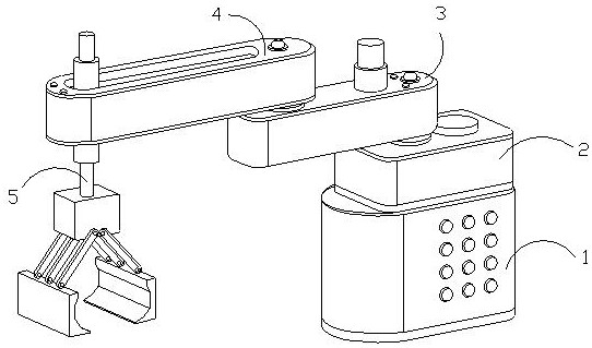
[0029] as attached figure 1 To attach Figure 5 Shown:

[0030] The invention provides an automatic control device for an industrial robot, the structure of which is provided with a control station 1, a drive transfer box 2, a transmission frame 3, an activity control device 4, and a grabbing device 5, and the drive transfer box 2 is installed above the control station 1 , the transmission frame 3 is connected to the top of the drive case 2 and is movably matched, the activity control device 4 is in transmission cooperation with the front end of the transmission frame 3 , and the grasping device 5 is slidably matched with the inside of the activity control device 4 .

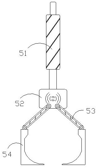
[0031] The grasping device 5 is provided with a driving column 51, an induction machine 52, a matching rod 53, and a robot gripper 54. The driving column 51 is slidingly matched with the inside of the movable control device 4, and the induction machine 52 is fixedly connected to the driving column 51. At the l...

Embodiment 2

[0037] as attached Figure 6 to attach Figure 7 Shown:

[0038] Wherein, the connecting frame a2 is provided with an arc frame a21, a swing rod a22, a spring steel a23, a pulling block a24, and a solid block a25. Both ends of the arc frame a21 are hingedly connected with the solid block a25, and the swing rod a22 One end is hingedly connected to the solid block a25, the spring steel a23 is slidingly fitted between the swing rods a22, the pulling block a24 is connected between the ends of the swing rod a22, and the arc frame a21 is arc-shaped and has a telescopic The swing rod a22 can be pivoted and folded, and the pulling block a24 is a block made of butadiene rubber, which has good traction. The swing rod a22 is made of spring steel a23 and the pulling block a24 With the cooperation of the spacer, the spacing can be changed, which is convenient for the overall inclination of the swing rod a22 to change, and the force applied to the arc frame a21 is different, which is cond...


PUM


Abstract

The invention discloses an automatic control device for an industrial robot. The automatic control device is structurally provided with a power control station, a driving rotating box, a transmission frame, a movable control device and a grabbing device; the driving rotating box is mounted above the power control station; the transmission frame is connected to the upper portion of the driving rotating box and is in movable fit with the driving rotating box; the movable control device is in transmission fit with the front end of the transmission frame; the grabbing device is in sliding fit with the inner side of the movable control device; and a driving column slides in a channel in a reciprocating mode, the outer end face of the driving column makes contact with a shoveling and scraping device continuously, a connecting frame assists a shoveling block to generate position change along with different extrusion force, thus, the contact pressure borne by the shoveling block is relieved in time, and the driving column is prevented from being hindered in the sliding process; and meanwhile, the angular shoveling block makes contact with the driving column, certain abutting force can be generated on the outer side of the driving column to serve as shoveling and scraping acting force under moving of the driving column, and thus waste scraps generated due to abrasion of the outer side of the driving column can be shoveled down conveniently and cleaned in time.

Description

technical field [0001] The invention belongs to the field of robot automation, and more specifically, relates to an industrial robot automation control device. Background technique [0002] With the rapid development of modern technology, robot technology is also becoming more and more mature, and it is widely used in the industrial field. The level of industrial robots has been continuously improved, and the automation of industrial operations can be completed under control, reducing labor force and increasing industrial productivity. [0003] Based on the inventor's discovery above, the existing industrial robot automation control device has the following deficiencies: [0004] After the data parameters are manipulated, the robotic automation control device can complete the actions of grabbing, transposing, and placing objects by itself. To complete these actions smoothly, it is necessary to ensure that the driving column can slide stably in the displacement rail, which is...

Claims


Application Information

Patent Timeline
Patent Type & Authority Applications(China)
IPC IPC(8): B25J13/00B25J13/06B25J13/08B25J15/08B25J19/00
CPCB25J13/00B25J13/06B25J15/08B25J13/08B25J19/0058
Inventor 李进华罗柱林蓝李敏
Owner 李进华
Why Eureka
Try Eureka