
Control method and control system of hydraulic retarder

A hydraulic retarder and control method technology, applied in the direction of liquid resistance brakes, brakes, brake types, etc., can solve the problems affecting economy and maneuverability, difficult to open the hydraulic retarder correctly, and prone to false triggering , to achieve good economy, reduce the loss of brake pads, and reduce the cost of loss

Pending Publication Date: 2022-01-21
XIAMEN YAXON NETWORKS CO LTD
View PDF1 Cites 2 Cited by
  • Summary
  • Abstract
  • Description
  • Claims
  • Application Information

AI Technical Summary

Problems solved by technology

However, the hydraulic retarder requires the process of filling the brake fluid into the retarder to generate braking force, and has a hysteresis effect in response time, so it is not suitable for real-time or emergency braking.
[0003] At present, the hydraulic retarder is generally opened manually by the driver, and it is mostly used on long downhills to reduce wear on the friction braking system. However, most drivers are still accustomed to only stepping on the brakes, and it is difficult Ensure that the hydraulic retarder can be opened correctly
In order to realize the automatic control of the hydraulic retarder, the patent No. CN201510321728, the Chinese patent with the patent name "Control System and Control Method of the Hydraulic Retarder" combines the opening and closing of the hydraulic retarder with the depth of the brake pedal, but this This simple combined control method is prone to false triggering, which affects economy and maneuverability

Method used


Image

  • Control method and control system of hydraulic retarder
  • Control method and control system of hydraulic retarder
  • Control method and control system of hydraulic retarder

Examples


Embodiment Construction

[0045] In order to make the object, technical solution and advantages of the present invention clearer, the embodiments of the present invention will be further described in detail below in conjunction with the accompanying drawings.

[0046] The execution subject of the method in this embodiment is the vehicle brake controller, and the vehicle brake controller can install the execution program and / or database program of the method in this embodiment, which is not specifically limited in the present invention.

[0047] It should be noted that the step identifications involved in the claims of the present application and the description are only for making the document look clearer, and the order of the steps can be adjusted accordingly according to requirements during specific implementation.

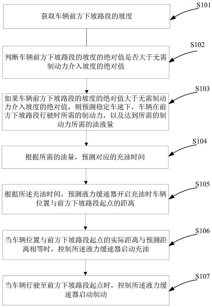
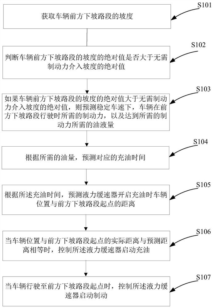
[0048] see figure 1 As shown, a method for controlling a hydraulic retarder provided by an embodiment of the present invention includes:

[0049] S101, acquiring the gradient of the do...


PUM


Abstract

The invention discloses a control method and system for a hydraulic retarder. The control method comprises the steps: acquiring the gradient of a downhill road section in front of a vehicle; judging whether the absolute value of the slope of the downhill road section in front of the vehicle is greater than that of the braking force intervention-free slope; if so, predicting the braking force needed when the vehicle runs on the slope of the downhill road section in front and the oil amount needed for reaching the braking force at the stable vehicle speed; predicting corresponding oil filling time according to the oil quantity; according to the oil charging time, predicting the distance between the vehicle and the starting point of the downhill road section in front when the hydraulic retarder starts to charge oil; when the actual distance between the vehicle and the starting point of the downhill road section in front is equal to the predicted distance, controlling the hydraulic retarder to start oil charging; and when the vehicle runs to the starting point of the downhill road section in front, controlling the hydraulic retarder to start braking. The hydraulic retarder is started to charge oil before the vehicle reaches the downhill position, and the hydraulic retarder is started to brake when the vehicle reaches the downhill position, so that the loss of brake pads is reduced, and the running cost loss of the vehicle is reduced.

Description

technical field [0001] The invention relates to the field of vehicle control, in particular to a control method and a control system of a hydraulic retarder. Background technique [0002] The wear of the brake pads is very serious when the heavy-duty truck brakes, and the physical friction brake has the problem of thermal failure. Retarder is another type of braking system on heavy trucks, especially hydraulic retarder, which has the advantages of timely conduction of braking heat, and is simple in structure, safe and convenient. However, the hydraulic retarder requires the process of filling the brake fluid into the retarder to generate braking force, and has a hysteresis effect in response time, so it is not suitable for real-time or emergency braking. [0003] At present, the hydraulic retarder is generally opened manually by the driver, and it is mostly used on long downhills to reduce wear on the friction braking system. However, most drivers are still accustomed to on...

Claims


Application Information

Patent Timeline
Patent Type & Authority Applications(China)
IPC IPC(8): B60T10/00F16D57/02
CPCB60T10/00F16D57/02B60T1/087B60T10/02F16D57/04B60W2552/15B60K31/06B60T2201/04B60T2210/20B60W10/196B60W2710/18B60Y2300/181B60Y2300/18108B60Y2400/81
Inventor 涂岩恺陈远
Owner XIAMEN YAXON NETWORKS CO LTD
Learn More