
Switch switching circuit for LED

A technology of LED lights and LED modules, applied in the electronic field, can solve problems such as wrong switching, wrong switching, and failure to find zero values, etc., to achieve the effect of solving false triggers and simplifying external control

Inactive Publication Date: 2016-07-20
UNIV OF ELECTRONIC SCI & TECH OF CHINA
View PDF5 Cites 0 Cited by
  • Summary
  • Abstract
  • Description
  • Claims
  • Application Information

AI Technical Summary

Problems solved by technology

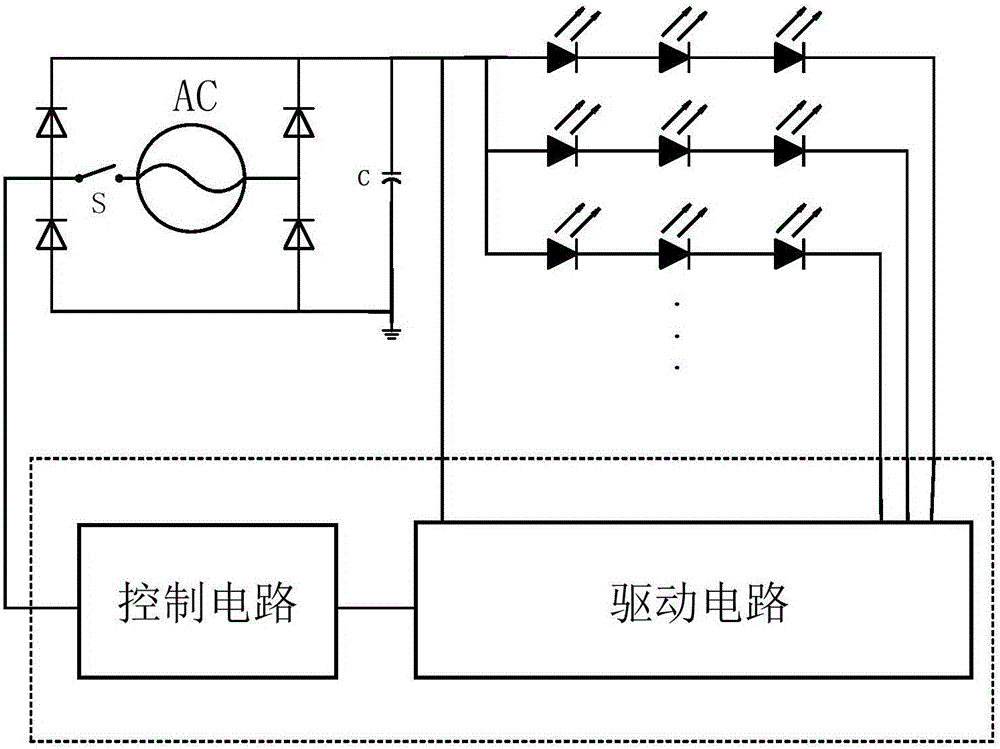
But this method also has such a problem, that is, the problem of the detection point. Since the LED mostly uses 50Hz alternating current, a zero value will be generated every 10ms
Detecting the rectifier bridge port will cause wrong switching, that is, wrong switching may occur every 10ms
However, if the waveform after capacitance shaping is detected, the zero value corresponding to switching cannot be found on the waveform.

Method used


Image

  • Switch switching circuit for LED
  • Switch switching circuit for LED
  • Switch switching circuit for LED

Examples


Embodiment Construction

[0012] Below in conjunction with accompanying drawing, describe technical scheme of the present invention in detail:

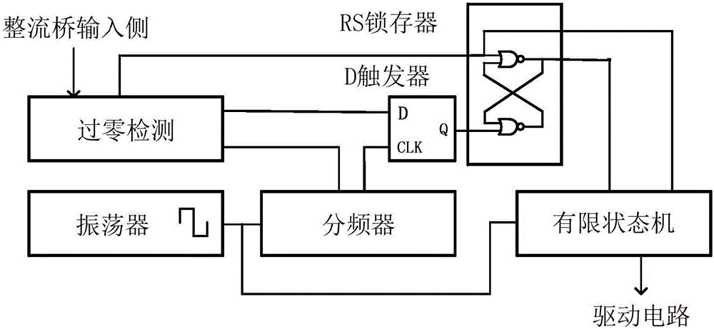
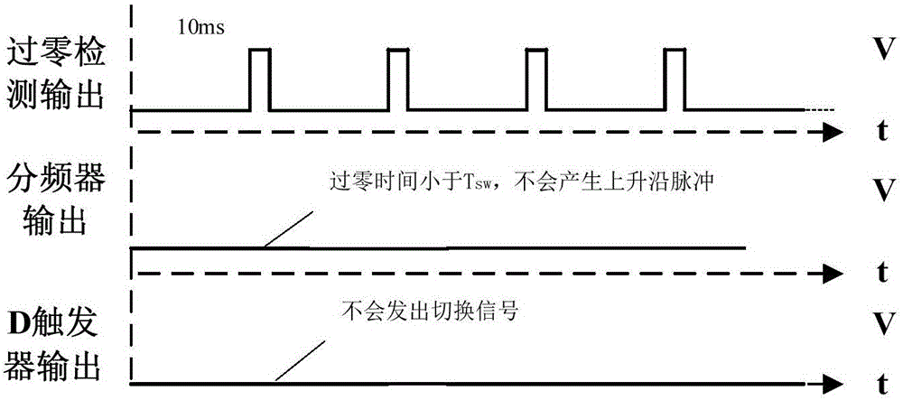
[0013] like figure 1 As shown, the additional circuit of the present invention can be integrated in the LED control chip. The specific structure is as figure 2 As shown, among them, the oscillator unit will continuously provide clock signals to the frequency divider unit and the finite state machine unit. The function of the zero-crossing detection module is to detect whether the input terminal of the rectifier bridge is zero, and the function of holding and clearing is placed inside. If it is judged to be zero at the input side of the rectifier bridge, the zero-crossing detection unit will send the enable signal to the frequency division The device unit and the D terminal of the D flip-flop unit. The frequency divider unit will only divide the frequency of the square wave of the oscillator when there is a zero-crossing detection signal, and usually block ...


PUM


Abstract

The present invention belongs to the field of the electronic technology, and specifically relates to a switch switching circuit for a LED. The switch switching circuit comprises a power supply, a LED module, a driving circuit and a control circuit; the LED module is connected with the power supply and the driving circuit, the control circuit is connected with the power supply and the driving circuit, and the control circuit is configured to control the switching of the LED lamps in the LED module and the switching between different LED lamps. The switch switching circuit for LED solves the contradiction between the detection switch points and the false triggering, is the simplest in really required outside control, and realizes two functions of the switching of a LED lamp and the switching between LED lamps.

Description

technical field [0001] The invention belongs to the field of electronic technology, and in particular relates to a switch switching circuit for LEDs. Background technique [0002] In LED lighting technology, LED drive circuit is one of the key links. Common LED drive methods include constant current, constant voltage, current limiting, and pulse. With the mass and large-scale use of LED lights, a streamlined, intuitive and convenient control circuit is very necessary. For the need of a single switch to control the on and off of multiple LED lights, the common method is to install a device such as a segment switch, which uses an additional peripheral circuit design, adding a decoder, power supply circuit, relay , switches and other additional control modules to control the corresponding LED switches, thus realizing the switching of LED lights. However, adding peripheral modules will seriously affect the complexity and cost of the product, and more modules may also increase...

Claims


Application Information

Patent Timeline
IPC IPC(8): H05B33/08H05B44/00
CPCH05B45/37Y02B20/30
Inventor 方健姚易寒杨舰李晨辰酒耐霞辛世杰朱弼文张波
Owner UNIV OF ELECTRONIC SCI & TECH OF CHINA
Learn More