

Water surface monitoring device
A technology of monitoring device and main equipment, applied in the direction of measuring device, lubrication indicating device, liquid level indicator, etc., can solve the problems of unstable working environment, easy to be damaged, unable to be fixed on the water surface, etc., and achieve good power generation effect , The effect of avoiding loss and convenient salvage
- Summary
- Abstract
- Description
- Claims
- Application Information
AI Technical Summary
Problems solved by technology
Method used
Image

Examples
Embodiment Construction
[0030] In order to make the technical means, creative features, goals and effects achieved by the present invention easy to understand, the present invention will be further described below in conjunction with specific embodiments.
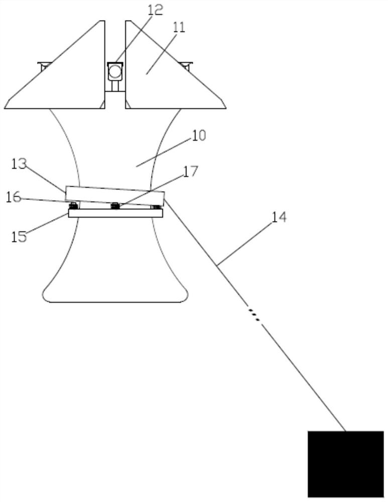
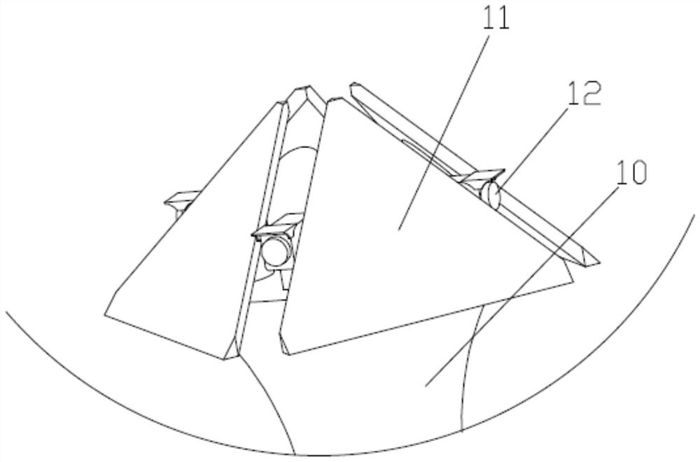
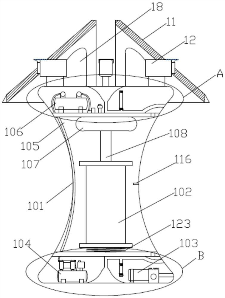
[0031] Such as Figure 1 to Figure 9 As shown, a water surface monitoring device includes a main equipment box 10 and a solar panel 11 and a camera 12 installed on the top of the main equipment box 10. The housing 101 of the main equipment box 10 is provided with an equipment box 102, a self-priming Pump 103, compressed air pump 104, upper connecting pipe 109 and lower connecting pipe 110;
[0032] An upper horizontal plate 111 and a lower horizontal plate 112 are fixedly connected in the housing 101, a sliding support plate 108 is fixedly connected between the upper horizontal plate 111 and the lower horizontal plate 112, and the equipment box 102 is slidably connected to the sliding support plate 108, and the bottom of the equipment box 102 is ...
PUM
 Abstract
Description
Claims
Application Information