Automatic workpiece spraying device

A technology for spraying devices and workpieces, applied in the directions of spraying devices, devices for coating liquid on surfaces, coatings, etc., can solve the problems of high production cost and processing cost, insufficient hot air efficiency and insufficient hot air efficiency of dispersion dryers, and achieves The effect of reducing production cost and processing cost, simple structure and ingenious design

Active Publication Date: 2022-01-25
CHONGQING INST OF ENG
View PDF11 Cites 3 Cited by
  • Summary
  • Abstract
  • Description
  • Claims
  • Application Information

AI Technical Summary

Problems solved by technology

[0002] In order to reduce manpower input in some processing factories, automation equipment is becoming more and more common in factories. The automatic completion of processing or production processes by equipment can effectively reduce labor costs and ensure the accuracy of processing. Today, the automation of spraying workpieces The equipment is also relatively common. The automatic spraying device is roughly divided into a painting unit and a drying unit. The workpiece is passed through the painting box and the drying box through the boom, and the painting and drying work is completed in sequence, and the entire automatic spraying process is completed. However, in order to ensure the complete drying of the surface of the workpiece in the drying box, the setting of the drying box is often long, so multiple hot air fans are needed to connect the drying box to ensure the supply of hot air to the drying box, so that the overall production The cost and processing cost are relatively high. If only one hot air blower is connected to the drying box, the hot air will pass through the entire drying box, which will disperse the hot air efficiency of a dryer, and the workpiece is in a moving state in the drying box, so the workpiece The hot air received in the drying box is not efficient enough

Method used


Image

  • Automatic workpiece spraying device
  • Automatic workpiece spraying device
  • Automatic workpiece spraying device

Examples


Embodiment Construction

[0031] In order to enable those skilled in the art to better understand the present invention, the technical solution of the present invention will be further described below in conjunction with the accompanying drawings and embodiments.

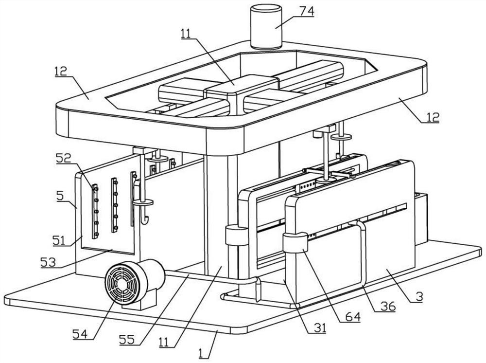
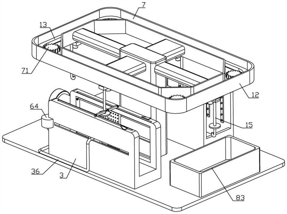
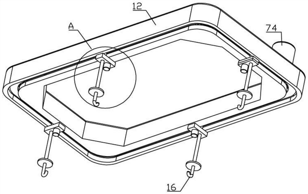
[0032] Such as Figure 1-10 As shown, an automatic workpiece spraying device of the present invention includes a base plate 1, a support column 11 is provided in the middle of the base plate 1, and a frame 12 is fixedly connected to the upper side of the support column 11. The frame 12 is equipped with a transmission mechanism, and the transmission mechanism is equipped with a transmission chain. 13. The lower side of the transmission chain 13 is equipped with a number of fixed rods 14, and the lower side of the fixed rods 14 is equipped with a suspension rod 15. The lower side of the suspension rod 15 is fixedly connected with a hook 16, and the upper side of the base plate 1 is provided with a painting unit and a drying unit;

[0033]The ...


PUM


Abstract

The invention belongs to the technical field of automatic machining, and particularly relates to an automatic workpiece spraying device. The automatic workpiece spraying device comprises a bottom plate, a transmission mechanism is provided with a transmission chain, a lifting hook is fixedly connected to the lower side of a lifting rod, and a paint spraying unit and a drying unit are arranged on the upper side of the bottom plate; a plurality of air spraying openings are formed in the surfaces of the opposite sides of two drying plates, drying hoses penetrating through sliding grooves are jointly assembled on the sides, away from each other, of the two drying plates, T-shaped rods extending out of rectangular step holes are fixedly connected to two springs, pulling mechanisms matched with the T-shaped rods are jointly assembled between L-shaped connecting pieces and a drying box, and rebounding mechanisms matched with the drying plates are arranged at the end, away from the pulling mechanisms, of a paint spraying box in a bilateral symmetry mode. After a workpiece is subjected to paint spraying treatment, the workpiece is moved into the drying box, the lifting rod is matched with the two T-shaped rods, the drying plates on the two sides are driven to move along with the workpiece all the time, it is guaranteed that the workpiece is located in the area with the highest hot air efficiency all the time in the drying box, and the workpiece drying efficiency is improved.

Description

technical field [0001] The invention belongs to the technical field of automatic processing, and in particular relates to an automatic workpiece spraying device. Background technique [0002] In order to reduce manpower input in some processing factories, automation equipment is becoming more and more common in factories. The automatic completion of processing or production processes by equipment can effectively reduce labor costs and ensure the accuracy of processing. Today, the automation of spraying workpieces The equipment is also relatively common. The automatic spraying device is roughly divided into a painting unit and a drying unit. The workpiece is passed through the painting box and the drying box through the boom, and the painting and drying work is completed in sequence, and the entire automatic spraying process is completed. However, in order to ensure the complete drying of the surface of the workpiece in the drying box, the setting of the drying box is often l...

Claims


Application Information

Patent Timeline
Patent Type & Authority Applications(China)
IPC IPC(8): B05B16/20B05B13/02B05D3/04
CPCB05B16/20B05B13/0264B05D3/0413Y02P70/10
Inventor 李新胡聪娟葛国秋钱雅楠
Owner CHONGQING INST OF ENG
Why Eureka
Try Eureka