
A passive clamping mechanism coupled with gears and pulleys

A gear belt, passive technology, applied in the direction of conveyor objects, non-rotational vibration suppression, transportation and packaging, etc., can solve the problems of parts wear, limited adjustment range, increase the complexity of mechanism structure, volume and weight, etc., and achieve reduction Instant impact, simple structure effect

Active Publication Date: 2022-05-17
WEST CHINA HOSPITAL SICHUAN UNIV
View PDF11 Cites 0 Cited by
  • Summary
  • Abstract
  • Description
  • Claims
  • Application Information

AI Technical Summary

Problems solved by technology

In order to increase the anthropomorphism of the hand, more joint degrees of freedom should be designed in the hand to increase the reliability of the mechanism, but the use of multi-drivers to control the clamping mechanism will increase the structural complexity, volume and weight of the mechanism; in addition, in order to better Accurately grasping complex shapes and fragile precision objects requires the gripping mechanism to have a certain degree of self-adaptability; the existing gripping mechanism often drives the clamping object continuously through the motor, and the installation of the motor and the use of electricity are in a certain range. To some extent, it limits the breadth of application
[0003] For example: Chinese invention patent document CN101767337B discloses a bevel gear-pulley coupling under-actuated two-joint robot finger device. This invention is driven by a motor, which leads to an additional installation space for the motor in the entire mechanism, which reduces the simplicity of the mechanism structure; The invention uses the decoupling method to adaptively cover the object and adapt to the shape of the object, but long-term decoupling will cause a certain degree of wear and tear on the parts
[0004] As another example, the Chinese invention patent document CN101214652B discloses a transitional underactuated robot finger device, which uses springs to store potential energy to achieve decoupling and underactuation to adapt to the surface of the grasped object, and has certain advantages under low control requirements. Self-adjusting function, but the entire adjustment range is limited, and the spring has a certain degree of wear after storing and releasing potential energy for a long time, and the movement accuracy of the mechanism needs to be further adjusted

Method used


Image

  • A passive clamping mechanism coupled with gears and pulleys
  • A passive clamping mechanism coupled with gears and pulleys
  • A passive clamping mechanism coupled with gears and pulleys

Examples


Embodiment Construction

[0033] In order to make the purposes, technical solutions and advantages of the embodiments of the present application clearer, the technical solutions in the embodiments of the present application will be clearly and completely described below in conjunction with the drawings in the embodiments of the present application. Obviously, the described embodiments It is a part of the embodiments of this application, not all of them. The components of the embodiments of the application generally described and illustrated in the figures herein may be arranged and designed in a variety of different configurations. Accordingly, the following detailed description of the embodiments of the application provided in the accompanying drawings is not intended to limit the scope of the claimed application, but merely represents selected embodiments of the application. Based on the embodiments in this application, all other embodiments obtained by persons of ordinary skill in the art without cr...


PUM


Abstract

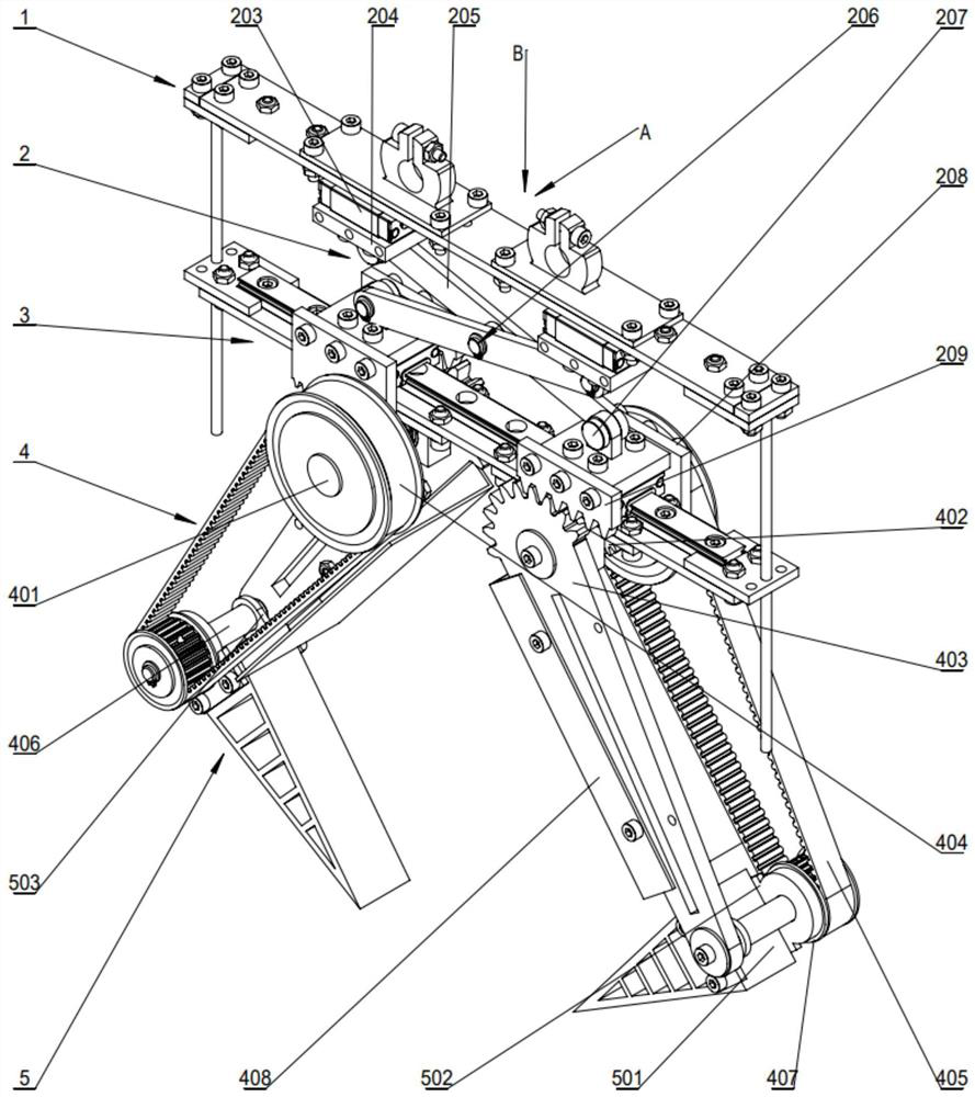
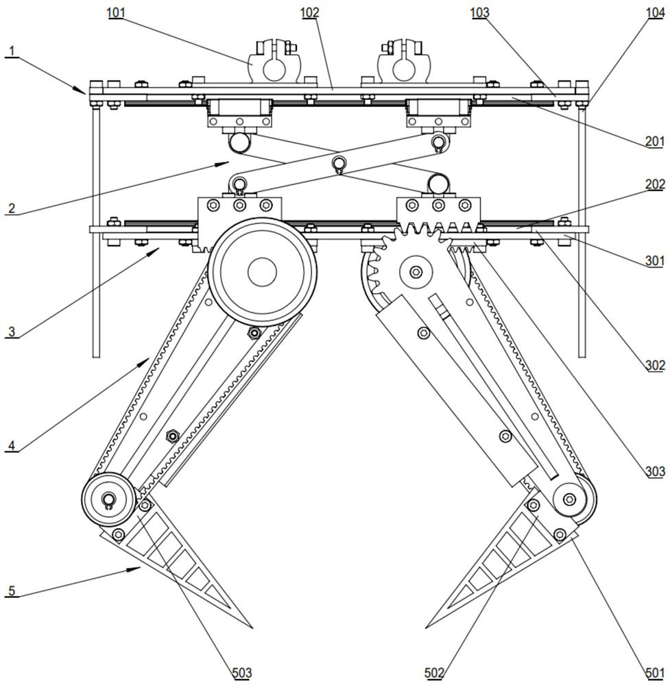
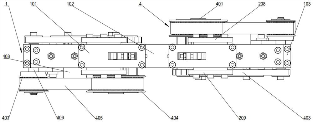
The invention discloses a passive clamping mechanism coupled with gears and pulleys, which comprises a connecting assembly sequentially connected from top to bottom, a scissor pressing rod assembly, a clamping mechanism connecting assembly, a rack and pinion coupling synchronous belt transmission assembly, and a flexible fin The effect component; the connection component is connected with the external pressure rod; the scissor type pressure rod component converts the vertical displacement of the external pressure rod into the horizontal displacement of the end of the scissor type pressure rod component; the clamping mechanism connection component is a rack and pinion coupling synchronous belt transmission component and The flexible fin-ray effect component provides support and fixation; the rack-and-pinion coupling synchronous belt drive component drives the flexible fin-ray effect component to move when the scissor pressure rod component moves; the flexible fin-ray effect component is driven by the rack-and-pinion coupling synchronous belt drive component Clamp the surface of round tubular objects. The clamping mechanism of the present invention uses the external pressing force on the clamping mechanism as the driving source, and through the change of the internal mechanical structure of the mechanism, the clamping mechanism realizes passive clamping without additional driving force.

Description

technical field [0001] The invention relates to the technical field of anthropomorphic robot hands, in particular to a passive clamping mechanism coupled with gears and pulleys. Background technique [0002] The mechanical gripping mechanism designed to imitate the gripping function of human hands has been applied to all aspects of life. In order to increase the anthropomorphism of the hand, more joint degrees of freedom should be designed in the hand to increase the reliability of the mechanism, but the use of multi-drivers to control the clamping mechanism will increase the structural complexity, volume and weight of the mechanism; in addition, in order to better Accurately grasping complex shapes and fragile precision objects requires the gripping mechanism to have a certain degree of self-adaptiveness; the existing gripping mechanism often drives the clamping object continuously through the motor, and the installation of the motor and the use of electricity are in a cert...

Claims


Application Information

Patent Timeline
Patent Type & Authority Patents(China)
IPC IPC(8): B65G47/90F16F15/02
CPCB65G47/90F16F15/02Y02E10/50
Inventor 李祥云
Owner WEST CHINA HOSPITAL SICHUAN UNIV
Learn More