
Adapter assembly

A technology of adapters and components, applied in the direction of pipes/pipe joints/pipes, elbows, pipe components, etc., can solve the problems of inconvenient disassembly and assembly of faucets, labor-intensive replacement of faucets, and waste of cost.

Active Publication Date: 2022-01-25
COOLER MASTER CO LTD
View PDF13 Cites 0 Cited by
  • Summary
  • Abstract
  • Description
  • Claims
  • Application Information

AI Technical Summary

Problems solved by technology

Since the disassembly and assembly of the previous faucet is not convenient, it is more convenient for the user to choose to replace the entire liquid cooling device than to replace the faucet with a lot of work.
However, although the replacement of the entire liquid cooling device can avoid the inconvenience of loading and unloading, it will additionally replace unnecessary components, resulting in waste of cost

Method used


Image

  • Adapter assembly
  • Adapter assembly
  • Adapter assembly

Examples


Embodiment Construction

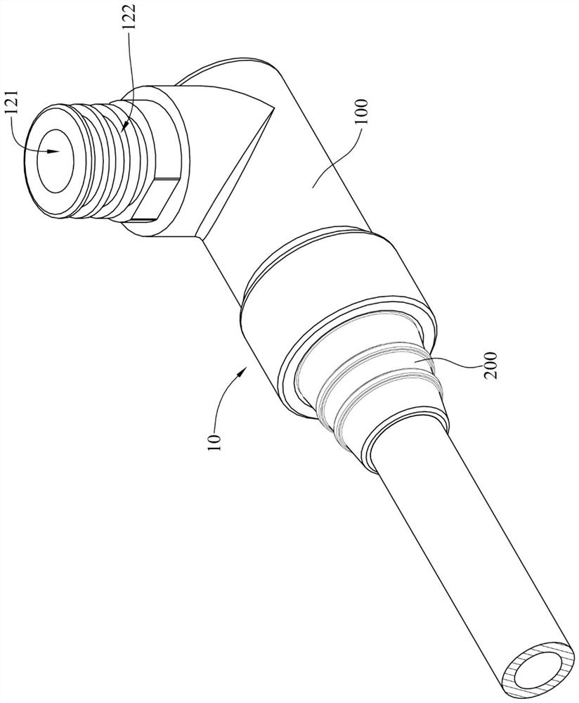
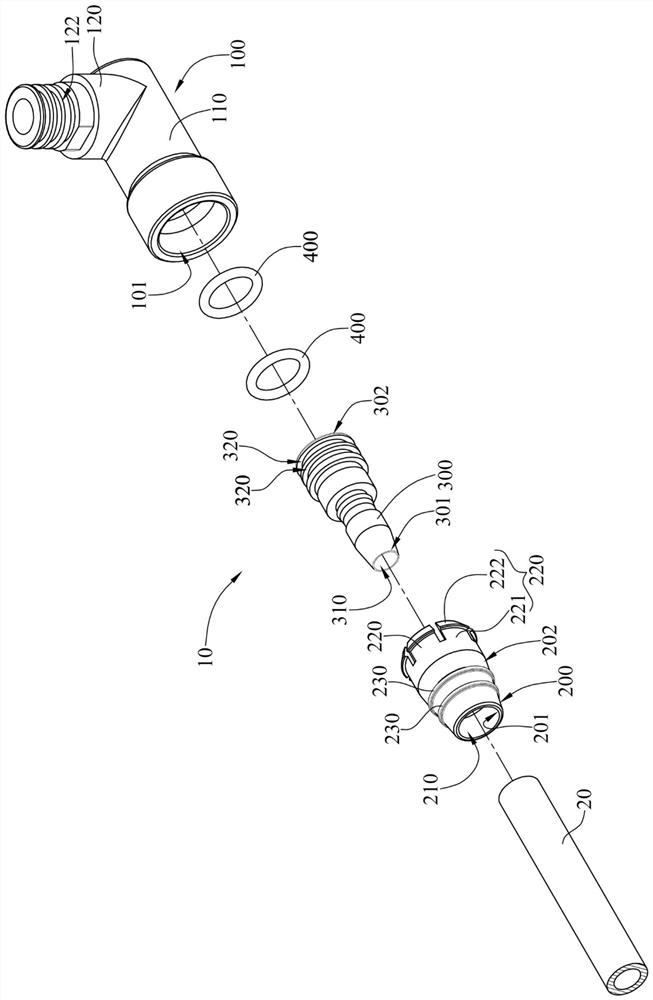
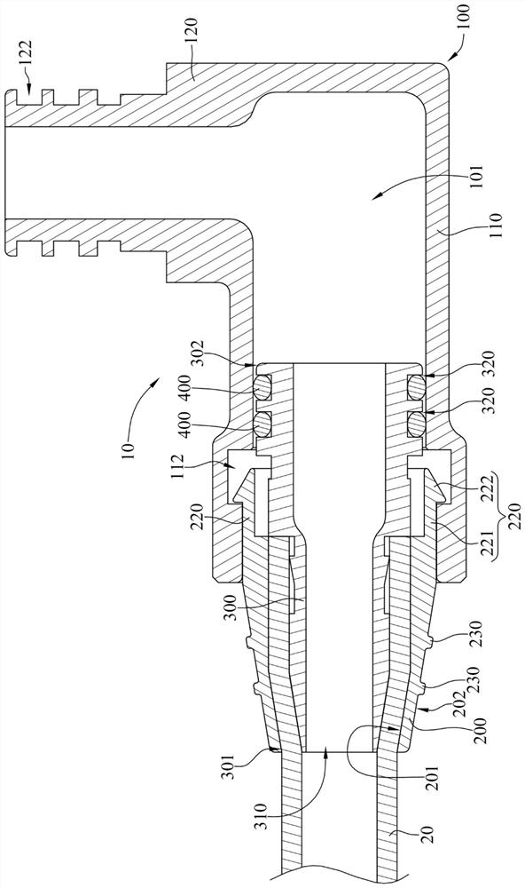
[0035] see Figure 1 to Figure 3 . figure 1 It is a three-dimensional schematic view of the adapter assembly according to the first embodiment of the present invention. figure 2 for figure 1 The decomposition diagram. image 3 for figure 1 sectional schematic diagram.

[0036] The adapter assembly 10 of this embodiment is used for connecting to a flow pipe 20 . The adapter assembly 10 includes a first joint 100 , a second joint 300 and a buckle ring 200 .

[0037] The first joint 100 includes a first ring segment 110 and a second ring segment 120 . The second ring segment 120 is connected to the first ring segment 110 and is substantially perpendicular to each other. The so-called substantially perpendicular to each other means perpendicular or nearly perpendicular due to manufacturing tolerances. The first joint 100 has a flow channel 101 , and the flow channel 101 runs through the first ring segment 110 and the second ring segment 120 .

[0038] The first ring segm...


PUM


Abstract

An adapter assembly is used for being connected to a flow pipe. The adapter assembly comprises a first connector, a second connector and a buckle ring sleeve. The first connector is provided with a flow channel and a buckling groove. The buckling groove is positioned in the flow channel. The second connector is provided with a first end, a second end and a flow channel. The second end is opposite to the first end, and the flow channel extends from the first end to the second end. The first end of the second connector is inserted into the flow pipe. The flow pipe is sleeved with the buckle ring sleeve, and at least part of the flow pipe is clamped between the buckle ring sleeve and the first end of the second connector. A buckle is arranged at one end of the buckle ring sleeve. The buckle ring sleeve is buckled in the buckle groove of the first connector through the buckle, so that the second end of the second connector is combined with the first connector, and the flow channel of the first connector is communicated with the flow channel of the second connector.

Description

technical field [0001] The invention relates to an adapter assembly, in particular to an adapter assembly for fluid transmission. Background technique [0002] Generally speaking, a processor is configured in an electronic device to process and analyze data. As the processing performance of the processor continues to increase, the heat generated by the processor is increasing. If the heat generated by the processor cannot be dissipated in time, the computing performance of the processor may be reduced due to high temperature. Therefore, in order to avoid the reduction of the computing performance of the processor, the user of the electronic device usually uses a liquid cooling device to dissipate the heat energy generated by the processor. [0003] In the current liquid cooling device, a faucet is usually installed to facilitate the connection of external pipelines. The diameter of the faucet is related to the heat dissipation efficiency of the liquid cooling device. The ...

Claims


Application Information

Patent Timeline
Patent Type & Authority Applications(China)
IPC IPC(8): F16L43/02H05K7/20
CPCF16L43/02H05K7/20272Y02D10/00F16L33/225F16L37/098H05K7/20781F16L33/03F16L43/00
Inventor 张庭睿
Owner COOLER MASTER CO LTD
Learn More