
Equipment and method for shaping and processing bottom leather heel surface leather in shoe production

A processing equipment and heel technology, which is applied in the field of shaping and processing equipment for sole leather and heel skin, can solve the problems of lowering the temperature of the sanding position, cooling and removing impurities at the place that cannot be sanded, and achieve the effect of avoiding damage

Inactive Publication Date: 2022-01-28
赵先平
View PDF5 Cites 1 Cited by
  • Summary
  • Abstract
  • Description
  • Claims
  • Application Information

AI Technical Summary

Problems solved by technology

[0006] Aiming at the deficiencies of the prior art, the present invention provides a device and method for shaping and processing the heel skin of the bottom leather in the production of shoes. At the same time, pulse blowing is performed on the sanding position, so that the temperature of the sanding position is rapidly reduced, and at the same time, the impurities in the sanding area are cleaned up, which solves the problem of only clamping the lower end of the heel skin and sanding There is a large error in grinding, and it is impossible to cool down and remove impurities at the sanding place

Method used


Image

  • Equipment and method for shaping and processing bottom leather heel surface leather in shoe production
  • Equipment and method for shaping and processing bottom leather heel surface leather in shoe production
  • Equipment and method for shaping and processing bottom leather heel surface leather in shoe production

Examples


Embodiment 1

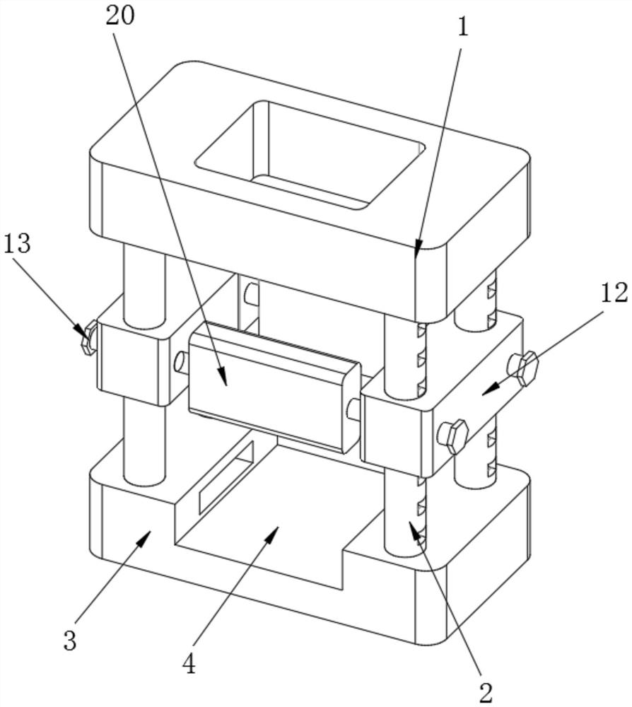
[0043] see Figure 1-3 , a kind of equipment for shaping and processing bottom leather and heel skin in shoe production, comprising a frame 1, the bottom of the frame 1 is fixedly connected with a support frame 2, the side wall of the support frame 2 is provided with grooves, and the grooves The diameter is the same as that of the locking bolt 13 , and the locking bolt 13 can engage the mounting frame 12 and the support frame 2 to fix the mounting frame 12 when rotating inwardly.

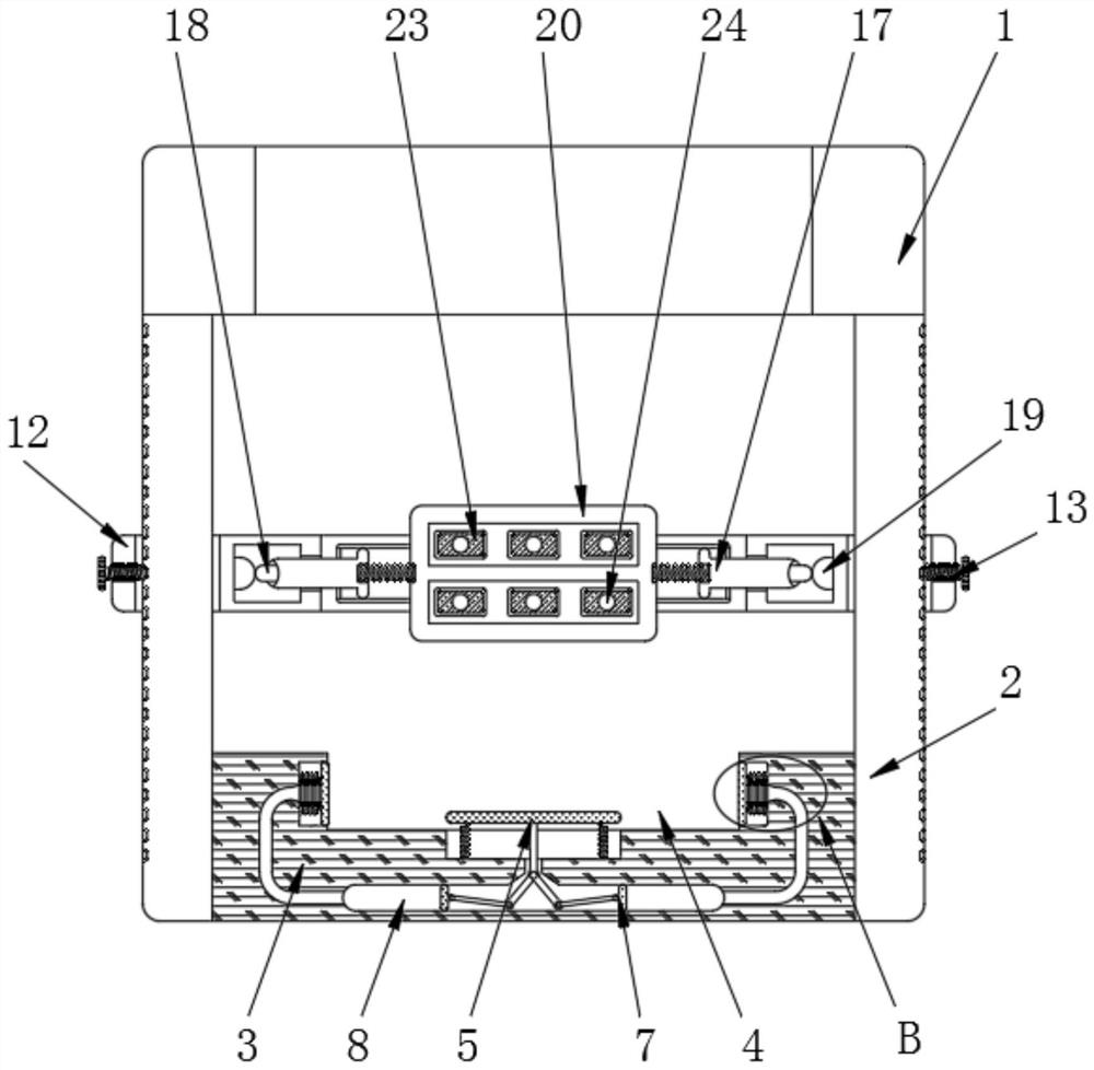
[0044] The end of the support frame 2 away from the frame 1 is fixedly connected with a base 3, and the inside of the base 3 is provided with a placement groove 4, and the inside of the center of the placement groove 4 is slidably connected with a pressing plate 5, and the bottom of the pressing plate 5 is rotatably connected with a movable connecting rod 6, The end of the movable connecting rod 6 away from the pressure plate 5 is rotatably connected with a blocking block 7, the blocking block 7 is ...

Embodiment 2

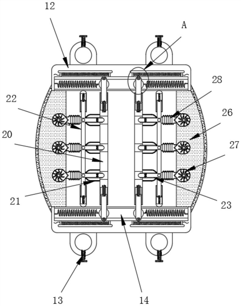
[0047] see Figure 2-4 , the surface of the support frame 2 is slidably connected with a mounting frame 12, the top of the mounting frame 12 is threadedly connected with a locking bolt 13, the inside of the side wall of the mounting frame 12 is provided with a chute 14, and the inside of the chute 14 is slidably connected with a slider 15 , the side of the slide block 15 close to the chute 14 is fixedly connected with a return spring 16, the upper surface of the slide block 15 is fixedly connected with a slide bar 17, and the end of the slide bar 17 close to the side wall of the chute 14 is fixedly connected with a metal contact 18, the metal The contact 18 is slidably connected to the surface of the resistance bar 19, and the metal contact 18 is connected with a power supply. The resistance bar 19 is connected with the resistance inside the air pump 27 through a wire. When the metal contact 18 slides to the outer end of the resistance bar 19, the air pump 27 The resistance co...

Embodiment 3

[0049] see Figure 3-7 , the inside of the side wall of the chute 14 is fixedly connected with a resistance strip 19, the outer surface of the sliding rod 17 is slidably connected with a sliding frame 20, the inside of the sliding frame 20 is provided with a through hole, and the elastic chamber 21 is fixedly connected to the side of the through hole, and The elastic cavity 21 is a hollow airtight cavity made of rubber, and the elastic cavity 21 can be squeezed to slide to one side of the sliding frame 20 .

[0050] The side of the sliding frame 20 away from the center of the mounting frame 12 is fixedly connected with an elastic cavity 21, and the end of the elastic cavity 21 away from the sliding frame 20 is fixedly connected with a push plate 22, and the side of the pushing plate 22 close to the elastic cavity 21 is fixedly connected with a clamping Block 23, the clamping block 23 is fixedly connected to the inside of the elastic cavity 21, and the clamping block 23 is loca...


PUM


Abstract

The invention relates to the technical field of leather shoe manufacturing, and discloses equipment for shaping and processing bottom leather heel surface leather in shoe production. The equipment comprises a rack, a support frame is fixedly connected to the bottom of the rack, a base is fixedly connected to one end, far away from the rack, of the support frame, a placement groove is formed in the base, a pressing plate is slidably connected to the interior of the center of the placement groove, a movable connecting rod is rotatably connected to the bottom of the pressing plate, a blocking block is rotatably connected to the end, away from the pressing plate, of the movable connecting rod, and an air cavity is formed in the position, close to the outer side of the blocking block, of the base. The lower end of the heel surface leather is clamped through the clamping plate, and meanwhile, when the mounting frame slides towards the two sides, the air pump can be triggered to work, and the clamping block is pushed through a push plate to clamp the upper end of the heel surface leather, so that the effects that the upper end and the lower end of the heel surface leather can be clamped separately, and the heel surface leather is prevented from deviating during sanding to cause sanding errors are achieved.

Description

technical field [0001] The invention relates to the technical field of leather shoe manufacturing, in particular to a device and method for shaping and processing sole leather and heel skin in shoe production. Background technique [0002] In the manufacture of leather shoes, the heel leather is a very important part of shoe manufacturing. The quality of the bottom leather correction directly determines the aesthetics and comfort of the heel leather. The bottom leather needs to be polished many times to make its surface smooth. , In order to avoid excessive grinding during grinding, it is generally necessary to fix the heel skin, and a fixing device is required. [0003] Nowadays, the fixing device used when grinding the heel skin only fixes the bottom of the heel skin, and does not fix the upper end, which is inconvenient for grinding. However, the heel skin has a certain lateral twist, which makes it easy to produce errors during grinding. , the surface of the bottom leat...

Claims


Application Information

Patent Timeline
Patent Type & Authority Applications(China)
IPC IPC(8): A43D8/00A43D8/16B24B19/00B24B41/06B24B55/02B24B55/06
CPCA43D8/00A43D8/16B24B19/00B24B41/06B24B55/02B24B55/06
Inventor 赵先平
Owner 赵先平
Learn More